

Down lamp
A technology of downlights and cooling tubes, which is applied to point light sources, lighting and heating equipment, fixed lighting devices, etc., can solve the problems of troublesome installation and disassembly, unsatisfactory heat dissipation effect, etc., to achieve convenient installation and disassembly, improve heat dissipation effect, The effect of shrinking the volume
Active Publication Date: 2015-11-18
邳州市城洁保洁有限公司
View PDF6 Cites 52 Cited by
- Summary
- Abstract
- Description
- Claims
- Application Information
AI Technical Summary
Problems solved by technology
[0002] The existing radiators used for downlights are generally fixed in shape due to design defects. In order to increase the heat dissipation area, heat dissipation fins are generally densely distributed on the outer wall of the downlight, but the heat is concentrated on the outer wall of the downlight during the heat dissipation process. , the cooling effect is not ideal
Moreover, the existing downlight must be fixed by a snap ring, which is troublesome to install and disassemble.
Method used
View moreImage
Smart ImageViewing Examples

Examples
Embodiment 1
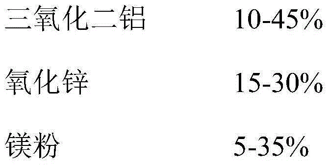
[0036] The foamed aluminum alloy material of the present invention consists of the following components by weight percentage:
[0037]
Embodiment 2
[0039] The foamed aluminum alloy material of the present invention consists of the following components by weight percentage:
[0040]
Embodiment 3
[0042] The foamed aluminum alloy material of the present invention consists of the following components by weight percentage:
[0043]
Login to View More PUM
 Abstract
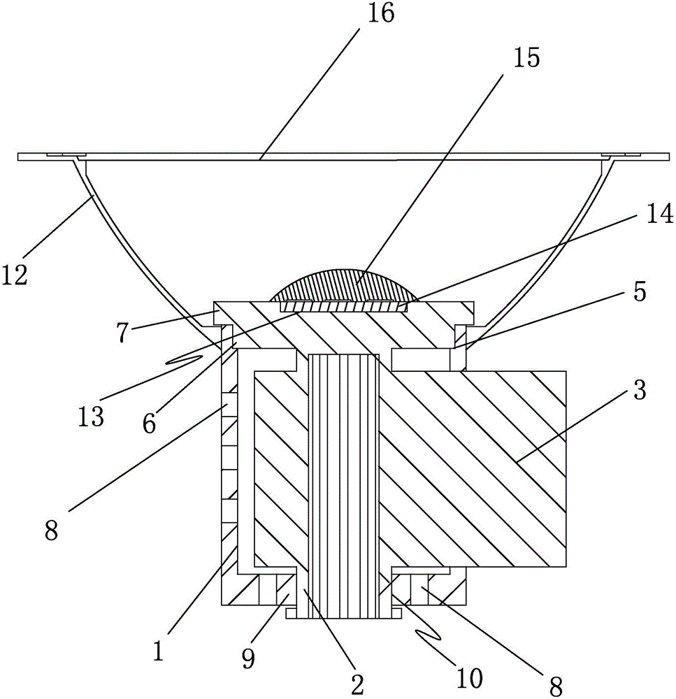
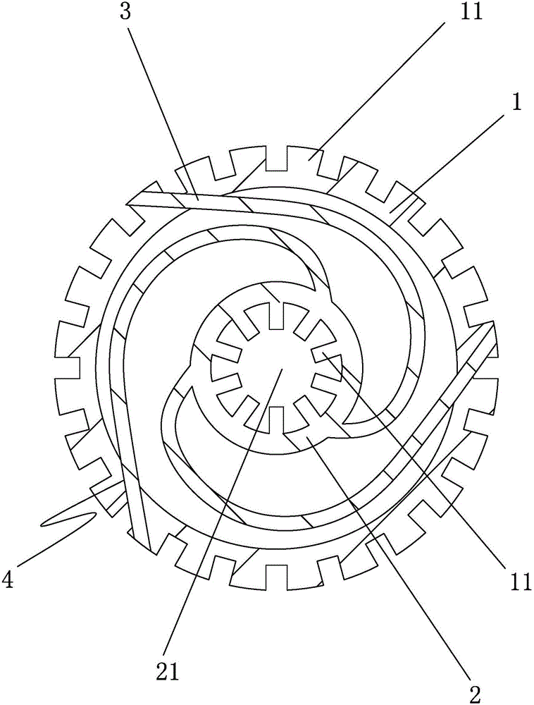
The invention discloses a down lamp. The down lamp is characterized in that the down lamp comprises a heat radiation cylinder body; a reflecting cover is connected with the upper end of the heat radiation cylinder body; a plurality of heat radiation fins are arranged on the outer wall of the heat radiation cylinder body; a heat radiator main body capable of rotating relative to the heat radiation cylinder body is arranged in the heat radiation cylinder body; a cavity is arranged in the heat radiator main body; heat radiation fins are distributed on the inner wall of the heat radiator main body evenly; a plurality of heat radiation sheets capable of huddling up on the heat radiator main body are arranged on the outer wall of the heat radiator main body; a plurality of guide grooves are formed in the heat radiation cylinder body; the heat radiation sheets are arranged in the guide grooves; an installing groove is formed in the upper end portion of the heat radiator main body; an LED chip is arranged in the installing groove. According to the down lamp, shortcomings in the prior art are overcome; the down lamp is simple in structure; a heat radiator can be unfolded, so that the down lamp is good in heat radiation effect and convenient to assemble and disassemble.
Description
technical field [0001] The invention relates to a downlight. Background technique [0002] The existing radiators used for downlights are generally fixed in shape due to design defects. In order to increase the heat dissipation area, heat dissipation fins are generally densely distributed on the outer wall of the downlight, but the heat is concentrated on the outer wall of the downlight during the heat dissipation process. , the heat dissipation effect is not ideal. Moreover, the existing downlights must be fixed by snap springs, and installation and disassembly are cumbersome. [0003] Therefore existing downlight needs to be further perfected. Contents of the invention [0004] The purpose of the present invention is to overcome the disadvantages of the prior art, and provide a downlight with simple structure, a radiator that can be deployed, a good heat dissipation effect, and convenient installation and disassembly. [0005] In order to achieve the above object, the...
Claims
Login to View More Application Information
Patent Timeline
 IPC IPC(8): F21S8/00F21V29/77F21V29/89F21V29/83F21Y101/02
CPCF21S8/00
Inventor黄亚宾
Owner邳州市城洁保洁有限公司