
Non-contact measuring system and method for drainage pipeline fluid flow

A drainage pipeline and measurement method technology, which is applied in the direction of liquid/fluid solid measurement, measurement flow/mass flow, measurement device, etc., can solve the failure, and the operator has to take out the equipment and clean it before reinstalling it at the bottom of the pipeline to measure Reduced precision, dangerous installation and operation of drainage pipes, etc., achieve the effect of light size, low overall power consumption, and reduced construction difficulty

Inactive Publication Date: 2015-11-18
SHANGHAI HANGZHENG MEASUREMENT & CONTROL SYST
View PDF7 Cites 20 Cited by
  • Summary
  • Abstract
  • Description
  • Claims
  • Application Information

AI Technical Summary

Problems solved by technology

This contact method has high requirements for the installation of the equipment. The installation must go deep into the bottom of the pipeline, and only qualified professionals can operate it, and the installation operation in the drainage pipeline has certain dangers.
In addition, if the measurement object is the fluid flow in the sewage pipe network, the surface of the measurement sensor will often be covered with silt after working for a period of time, which will reduce the measurement accuracy or even fail. The operator has to take out the equipment and clean it before reinstalling it. To the bottom of the pipe to continue the measurement

Method used


Image

  • Non-contact measuring system and method for drainage pipeline fluid flow
  • Non-contact measuring system and method for drainage pipeline fluid flow
  • Non-contact measuring system and method for drainage pipeline fluid flow

Examples


Embodiment Construction

[0034] In order to make the technical content disclosed in this application more detailed and complete, reference may be made to the drawings and the following various specific embodiments of the present invention, and the same symbols in the drawings represent the same or similar components. However, those skilled in the art should understand that the examples provided below are not intended to limit the scope of the present invention. In addition, the drawings are only for schematic illustration and are not drawn according to their original scale.

[0035] The specific implementation manners of various aspects of the present invention will be further described in detail below with reference to the accompanying drawings.

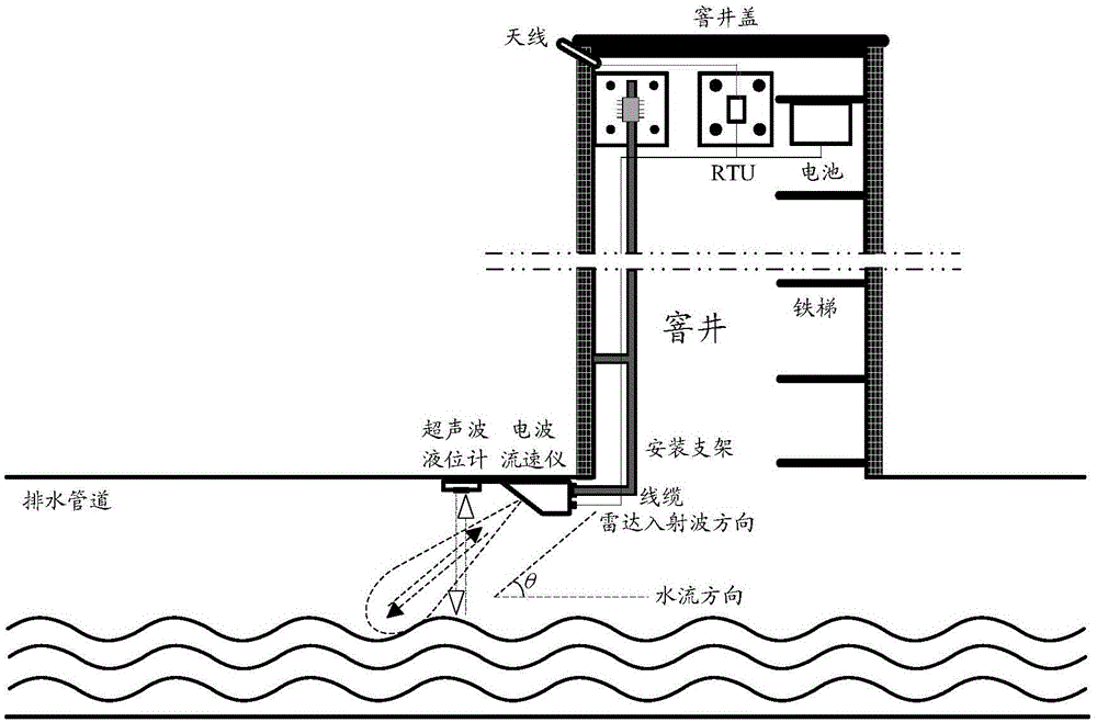
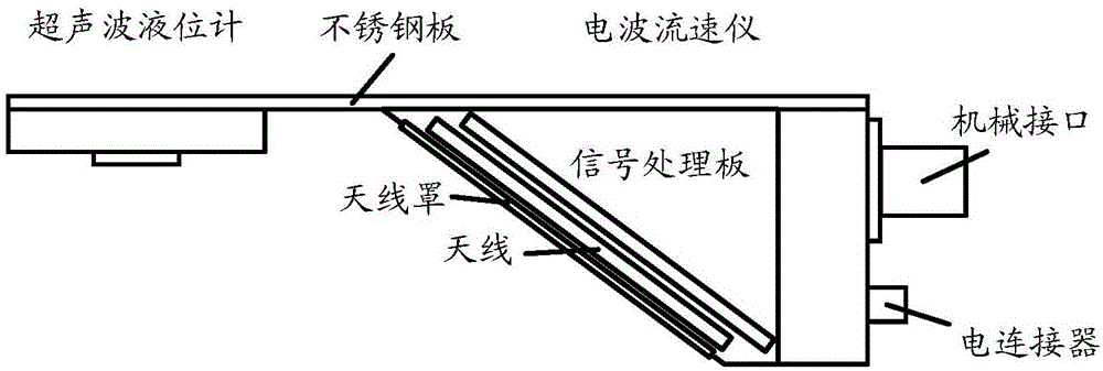
[0036] figure 1 A schematic diagram showing the application scene of the non-contact drainage pipe fluid flow measurement system of the present invention. figure 2 Shows figure 1 Schematic diagram of the structure of the measuring system of the electric...


PUM


Abstract

The invention provides a non-contact measuring system and method for drainage pipeline fluid flow. The measuring method comprises the steps that the surface flow rate of fluid is calculated according to the frequency of a transmitting wave and the frequency of radar echo with the combination of the angle of the jet liquid surface of the fluid; the liquid level of the fluid is calculated according to the sending and receiving time interval of ultrasonic pulses; the average flow rate of fluid inside the drainage pipeline is calculated according to the surface flow rate and the liquid level; the flow passage area of the fluid is calculated according to the liquid level and the radius of the pipeline; the instantaneous flow rate of the fluid is calculated according to the average flow rate and the flow passage area. Compared with the prior art, by the adoption of the non-contact measuring method, the surface flow rate and liquid level of the fluid inside the pipeline are measured, and then the instantaneous flow of the fluid is worked out. Due to the non-contact measurement, the problem of sludge sedimentation is avoided, and no periodic cleaning is needed. In addition, the measuring device is small in occupied space, low in total power consumption and convenient to install.

Description

technical field [0001] The invention relates to the field of measuring the surface velocity of liquids such as water and mud, in particular to a non-contact measurement system and method for fluid flow in drainage pipes. Background technique [0002] At present, the detection of drainage system in our country is in its infancy. The drainage pipe network includes the rainwater collection pipe network and the sewage pipe network. For a long time, most of the existing schemes have not carried out quantitative monitoring of the fluid in the pipe. At present, the flow measurement in the only few pipes still uses the contact method. The measurement method, ie, placing a measuring sensor in the liquid in order to obtain the velocity and level of the fluid. This contact method has high requirements for the installation of the equipment. The installation must go deep into the bottom of the pipeline, and only qualified professionals can operate it, and the installation operation in t...

Claims


Application Information

Patent Timeline
IPC IPC(8): G01F1/66
Inventor 陈德莉
Owner SHANGHAI HANGZHENG MEASUREMENT & CONTROL SYST
Learn More