Pulling plate structure for electric transformer core
A technology for power transformers and pulling plates, applied in the field of transformers, can solve problems such as no solution provided, and achieve the effect of eliminating local overheating and reducing eddy current loss
- Summary
- Abstract
- Description
- Claims
- Application Information
AI Technical Summary
Problems solved by technology
Method used
Image
Examples
corresponding approach 3
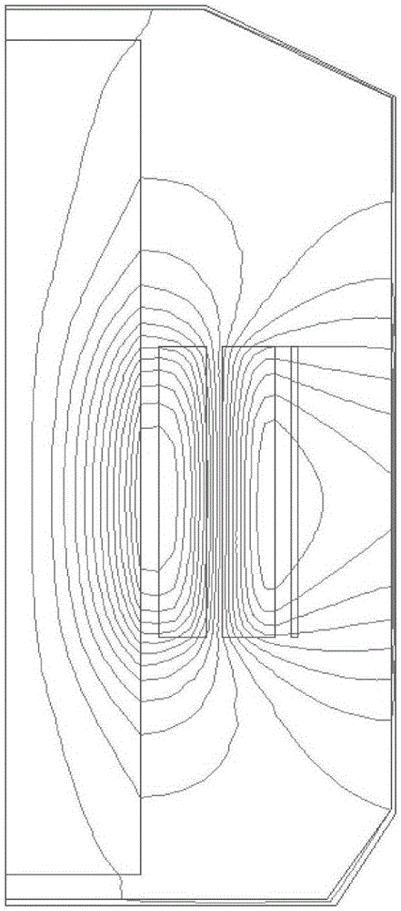
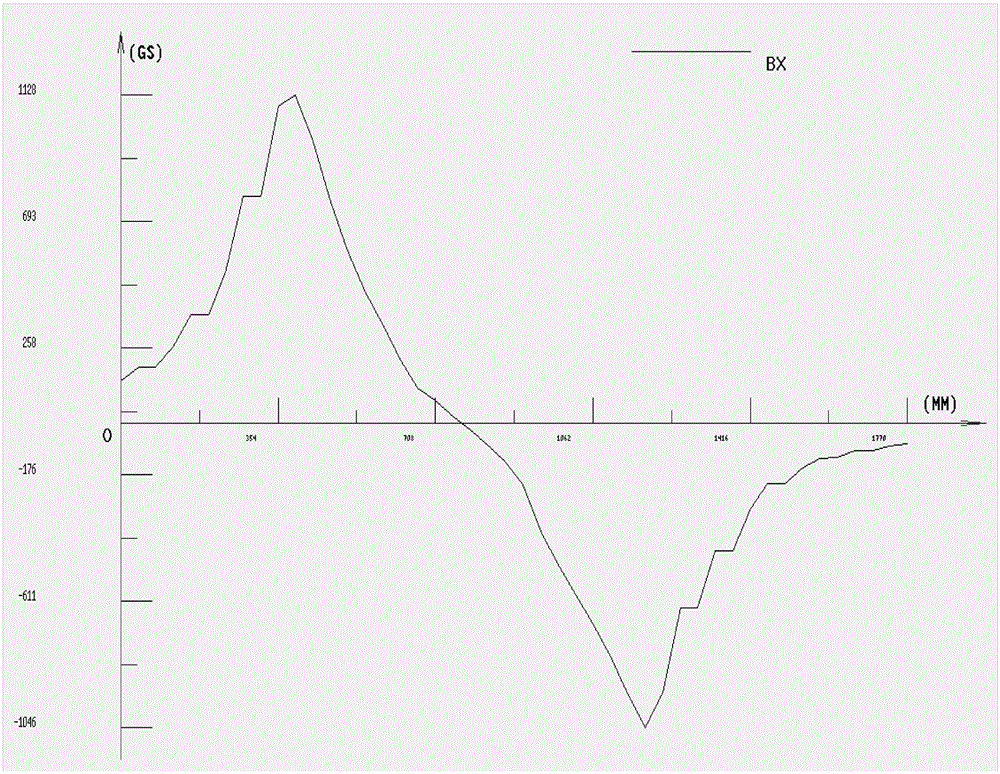
[0031] Figure 5 It is the eddy current distribution diagram provided by the preferred embodiment of the present invention with two elongated slots on the iron core pull plate of the power transformer. Corresponding to the third scheme, according to the calculation results of the leakage magnetic field above and the specific geometric dimensions of the relevant windings of the transformer, two slots are opened on the pull plate, which are extended by 80 mm below, that is, the slot length is 1080 mm.
[0032] According to the leakage field of the transformer winding and the distribution of the magnetic flux density on the surface of the iron core, the numerical calculation of the eddy current loss distribution of the iron core tie plate of the transformer is carried out. Table 1 is the calculation result of different pull plate structures of SZ11-50000 / 110 transformer.
[0033]
[0034] Table 1
[0035] From Table 1, it can be seen that Scheme 1 corresponds to opening a sl...
PUM
 Abstract
Description
Claims
Application Information
 - R&D
- Intellectual Property
- Life Sciences
- Materials
- Tech Scout
- Unparalleled Data Quality
- Higher Quality Content
- 60% Fewer Hallucinations
Browse by: Latest US Patents, China's latest patents, Technical Efficacy Thesaurus, Application Domain, Technology Topic, Popular Technical Reports.
© 2025 PatSnap. All rights reserved.Legal|Privacy policy|Modern Slavery Act Transparency Statement|Sitemap|About US| Contact US: help@patsnap.com


