Liquid crystal electronically controlled zero-crossing scanning leaky-wave antenna based on comb-shaped waveguide

A leaky-wave antenna and comb-line technology, which is applied in the field of microwave antenna engineering, can solve problems such as difficult zero-crossing scanning and electronically controlled scanning leaky-wave antennas are difficult to work, and achieve the effects of large power capacity, low loss, and reduced leakage

Active Publication Date: 2017-11-03
北京超材信息科技有限公司
View PDF4 Cites 0 Cited by
  • Summary
  • Abstract
  • Description
  • Claims
  • Application Information

AI Technical Summary

Problems solved by technology

[0006] The purpose of the present invention is to solve the problem that the traditional electronically controlled scanning leaky wave antenna based on traditional electric adjustment elements such as varactor diodes is difficult to work in the microwave high frequency band and that the existing liquid crystal electronically controlled fixed frequency scanning leaky wave antenna is not easy to realize zero-crossing scanning and To solve the problem of specially designed bias circuit, a liquid crystal electronically controlled zero-crossing scanning leaky-wave antenna based on comb-shaped waveguide is provided

Method used


Image

  • Liquid crystal electronically controlled zero-crossing scanning leaky-wave antenna based on comb-shaped waveguide
  • Liquid crystal electronically controlled zero-crossing scanning leaky-wave antenna based on comb-shaped waveguide
  • Liquid crystal electronically controlled zero-crossing scanning leaky-wave antenna based on comb-shaped waveguide

Examples


specific Embodiment approach 1

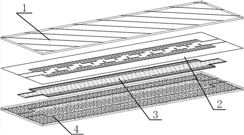
[0030] Specific implementation mode one: the following combination Figure 2 to Figure 5 Describe this embodiment mode, the liquid crystal electronically controlled zero-crossing scanning leaky wave antenna based on the comb-shaped waveguide in this embodiment mode, which includes a top dielectric plate layer 1, a metal layer 2, a liquid crystal layer 3 and a bottom waveguide groove 4;

[0031] A metal layer 2 is arranged between the top dielectric plate layer 1 and the bottom waveguide groove 4, and the bottom waveguide groove 4 is a rectangular plate with a longitudinal groove structure on the upper surface;

[0032] The top dielectric plate layer 1 and the metal layer 2 are tightly integrated into one body through mechanical processing, electroplating, hot pressing or microelectronic technology;

[0033] The bottom waveguide groove 4 is a rectangular plate with a vertical groove structure on the upper surface, and the liquid crystal material is filled between the vertical g...

specific Embodiment approach 2

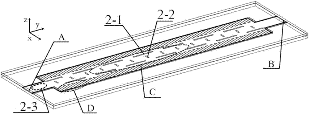
[0042] Specific implementation mode two: the following combination Figure 6 to Figure 13 This implementation mode is described, and the antenna structure of the first implementation mode is further described in this implementation mode in combination with specific examples.

[0043] As a special case, Figure 6 and Figure 7 The specific design parameters of a liquid crystal waveguide transverse and longitudinal slot leaky wave electronically controlled scanning antenna working at 13.3GHz are given. Depend on Figure 6 , the top dielectric plate of the antenna is a microwave substrate, and the relative permittivity ε r =4, loss tangent tanδ=0.004, thickness d 2 =1mm, the thickness of the metal layer is 0.017mm. The antenna consists of N=14 periodic slot units, the unit spacing p=7mm, and the conduction band length l c = 10.5 mm. The length of the longitudinal slit radiation unit is l 1 =10mm, the length of transverse seam l for matching 2 =1mm, distance between horiz...


PUM


Abstract

The liquid crystal electronically controlled zero-crossing scanning leaky wave antenna based on the comb-shaped waveguide belongs to the technical field of microwave antenna engineering. The frequency band and the existing liquid crystal electronically controlled fixed-frequency scanning leaky-wave antenna are not easy to achieve zero-crossing scanning and require a specially designed bias circuit. The invention includes a top dielectric plate layer, a metal layer, a liquid crystal layer and a bottom waveguide groove; a metal layer is arranged between the top dielectric plate layer and the bottom waveguide groove, and the bottom waveguide groove is a rectangular plate with a longitudinal groove structure on the upper surface; the metal layer It is a comb-like line structure, and N periodic slit units are arranged between two rows of comb teeth on the comb-like line structure. Transverse slits increase the equivalent series inductance when electromagnetic waves propagate between the bottom waveguide slot and the metal layer, and periodic longitudinal slits increase the equivalent parallel capacitance.

Description

technical field [0001] The invention belongs to the technical field of microwave antenna engineering. It can be widely used in modern wireless mobile communication, satellite communication in motion and various radar systems. Background technique [0002] Since the leaky wave antenna was proposed by W.W.Hansen in the 1940s, its unique radiation characteristics and excellent lobe scanning characteristics have made the leaky wave antenna a hot spot in the field of antenna research. The original leaky wave antenna is composed of a slotted rectangular waveguide, and its essence is that when the electromagnetic wave propagating on the waveguide structure is a fast wave, it will radiate part of the electromagnetic wave to the space. In recent decades, research on leaky-wave antennas has developed rapidly, especially planar leaky-wave antennas have been widely studied, because planar leaky-wave antennas can be directly processed on printed circuit boards (PCBs), with low profile, ...

Claims


Application Information

Patent Timeline
Patent Type & Authority Patents(China)
IPC IPC(8): H01Q1/22H01Q1/38H01Q23/00H01Q3/22
Inventor 孟繁义
Owner 北京超材信息科技有限公司
Why Eureka
Try Eureka