Substrate integrated waveguide-based loaded type Ka-band horn antenna

A substrate integrated waveguide and horn antenna technology, applied in the directions of waveguide horns, antennas, antenna arrays, etc., can solve the problem of low gain of horn antennas

Active Publication Date: 2015-11-18
HARBIN INST OF TECH
View PDF2 Cites 5 Cited by
  • Summary
  • Abstract
  • Description
  • Claims
  • Application Information

AI Technical Summary

Problems solved by technology

[0003] In order to solve the problem that the existing Ka-band H-plane horn antenna has low gain and cannot meet the act

Method used


Image

  • Substrate integrated waveguide-based loaded type Ka-band horn antenna
  • Substrate integrated waveguide-based loaded type Ka-band horn antenna
  • Substrate integrated waveguide-based loaded type Ka-band horn antenna

Examples


specific Embodiment approach 1

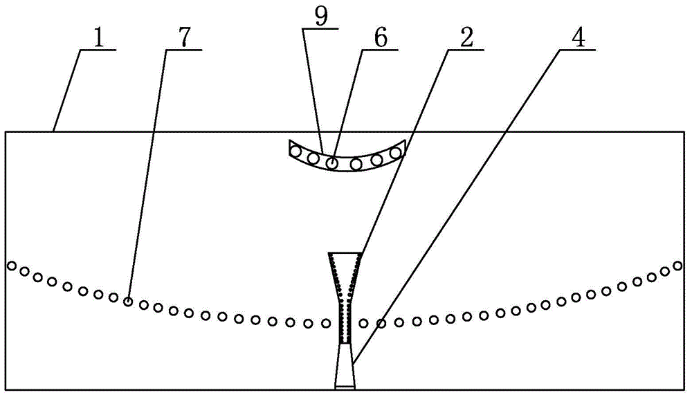
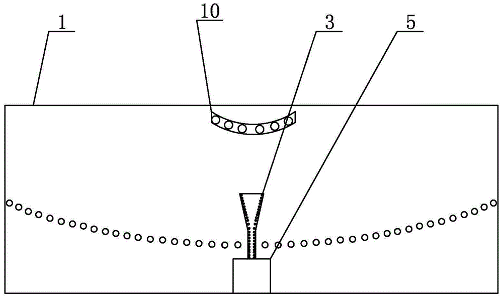
[0007] Specific implementation mode one: combine Figure 1 to Figure 4 This embodiment is described. The substrate-integrated waveguide-loaded Ka-band horn antenna described in this embodiment includes a dielectric substrate 1, a front horn structure 2, a rear horn structure 3, a front microstrip line 4, and a rear microstrip line 5. The dielectric substrate 1 is a rectangular plate. The upper metal layer 9 and the lower metal layer 10 are printed on the front and back of the dielectric substrate 1 respectively. The front speaker structure 2 is arranged in the middle and lower part of the front of the dielectric substrate 1, and the front speaker structure 2 is along the length direction. The center line of the dielectric substrate 1 is perpendicular to the center line along the length direction of the dielectric substrate 1, the lower end of the front speaker structure 2 is connected to the lower long side of the front surface of the dielectric substrate 1 through the front mi...

specific Embodiment approach 2

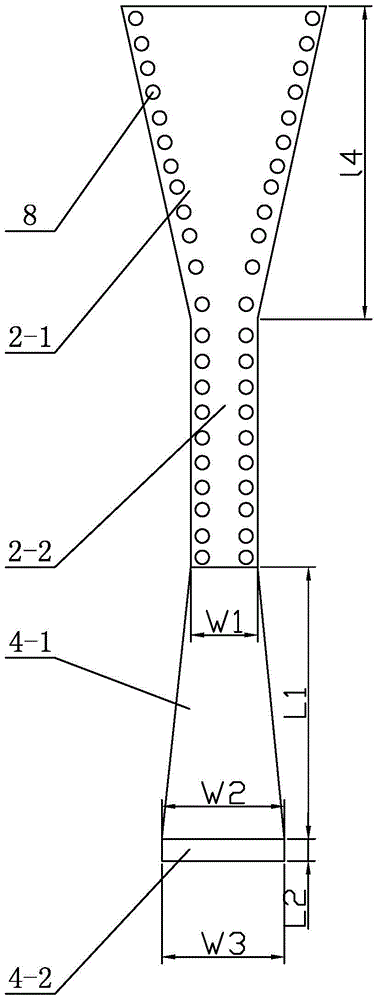
[0008] Specific implementation mode two: combination Figure 1 to Figure 4 To illustrate this embodiment, the front horn structure 2 of a loaded Ka-band horn antenna based on a substrate integrated waveguide described in this embodiment consists of a first inverted isosceles trapezoidal segment 2-1 and a first rectangular segment 2-2. It is connected sequentially from bottom to bottom, the short base of the first inverted isosceles trapezoidal segment 2-1 is connected to one short side of the first rectangular segment 2-2, and the other short side of the first rectangular segment 2-2 is connected to the front microstrip The upper end of the line 4 is connected, and the back speaker structure 3 is composed of the second inverted isosceles trapezoidal segment 3-1 and the second rectangular segment 3-2 sequentially connected from top to bottom, and the short bottom of the second inverted isosceles trapezoidal segment 3-1 The side is connected with a short side of the second recta...

specific Embodiment approach 3

[0010] Specific implementation mode three: combination Figure 1 to Figure 4 Describe this embodiment, the length of the dielectric substrate 1 of the loaded Ka-band horn antenna based on the substrate integrated waveguide described in this embodiment is 190 mm, the width of the dielectric substrate 1 is 74.5 mm, and the thickness of the dielectric substrate 1 is 3 mm. The relative dielectric constant of the dielectric substrate 1 is 4.4-4.6.

[0011] The technical effect of this embodiment is that: with such arrangement, the designed antenna can have a smaller structural size while satisfying the electrical specification. Other components and connections are the same as those in the first embodiment.

[0012] Specifically, the fourth method: combining Figure 1 to Figure 4 Describe this embodiment, the length L1 of the upper section 4-1 of the front microstrip line 4 of the loaded Ka-band horn antenna based on the substrate integrated waveguide described in this embodiment ...


PUM

PropertyMeasurementUnit
Lengthaaaaaaaaaa
Widthaaaaaaaaaa
Thicknessaaaaaaaaaa

Abstract

The invention relates to a Ka-band horn antenna, in particular, a substrate integrated waveguide-based loaded type Ka-band horn antenna. The objective of the invention is to solve the problems of low gain and incapability of satisfying actual requirements of an existing Ka-band H-surface horn antenna. The substrate integrated waveguide-based loaded type Ka-band horn antenna of the invention comprises a dielectric substrate, a front-surface horn structure, a back-surface horn structure, a front-surface microstrip line and a back-surface microstrip line; the dielectric substrate is a rectangular plate body; the front surface and back surface of the dielectric substrate are respectively printed with an upper metal layer and a lower metal layer; the front-surface horn structure is arranged at the middle lower part of the front surface of the dielectric substrate; the center line of the front-surface horn structure along the length direction of the front-surface horn structure is vertical to the center line of the dielectric substrate along the length direction of the dielectric substrate; and the lower end of the front-surface horn structure is connected with the lower long edge of the front surface of the dielectric substrate through the front-surface microstrip line. The antenna of the invention is applied to the wireless communication field.

Description

technical field [0001] The invention relates to a Ka-band horn antenna, in particular to a loaded Ka-band horn antenna based on a substrate integrated waveguide, which belongs to the field of wireless communication. Background technique [0002] It is not complicated to use substrate integrated waveguide technology as a feed structure, so it has been widely used in the design of planar horn antennas, such as H-plane horn antennas. Using reflectors to optimize the distribution of the aperture field can also achieve results such as high gain or low sidelobes. Since the gain of a single H-plane horn antenna is low, the application of this type of antenna is limited, so it is an effective method to load a reflector on the horn antenna to achieve high gain. Contents of the invention [0003] In order to solve the problem that the existing Ka-band H-plane horn antenna has low gain and cannot meet actual needs, the invention further proposes a loaded Ka-band horn antenna based o...

Claims


Application Information

Patent Timeline
IPC IPC(8): H01Q13/02H01Q21/00H01Q1/38
Inventor 林澍王蕾赵志华刘冠君宗华谷海川张丙琳
Owner HARBIN INST OF TECH
Why Eureka
Try Eureka