Motor rotor shaft automatic assembling machine

A technology for motor rotor shafts and rotor shafts, applied in the manufacture of stators/rotor bodies, etc., can solve problems such as low assembly efficiency, poor concentricity of rotor shafts, tilting of rotor shafts, etc., to reduce labor intensity of workers, improve product quality, and improve The effect of production efficiency

Inactive Publication Date: 2015-11-18
江门市智能装备制造研究院有限公司
View PDF4 Cites 18 Cited by
  • Summary
  • Abstract
  • Description
  • Claims
  • Application Information

AI Technical Summary

Problems solved by technology

This assembly method requires manual insertion of the rotor shaft, labor intensity, low assembly efficiency, and relying on manual insertion of the rotor shaft into the iron core, the concentricity between the rotor shaft and the iron core is poor, and it is easy to cause the rotor shaft to tilt when pressed into the iron core , resulting in deformation of the iron core and affecting the product qualification rate

Method used


Image

  • Motor rotor shaft automatic assembling machine
  • Motor rotor shaft automatic assembling machine
  • Motor rotor shaft automatic assembling machine

Examples


Embodiment Construction

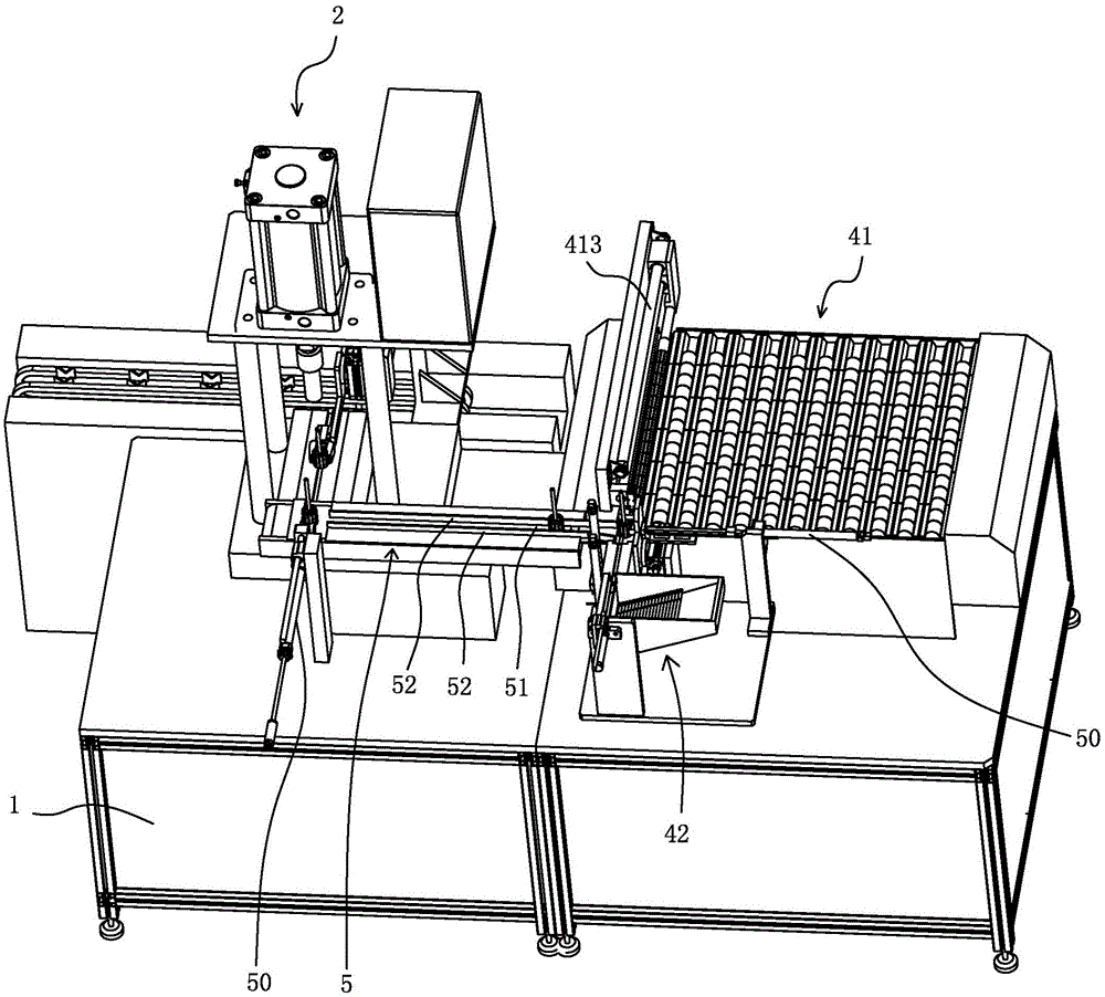
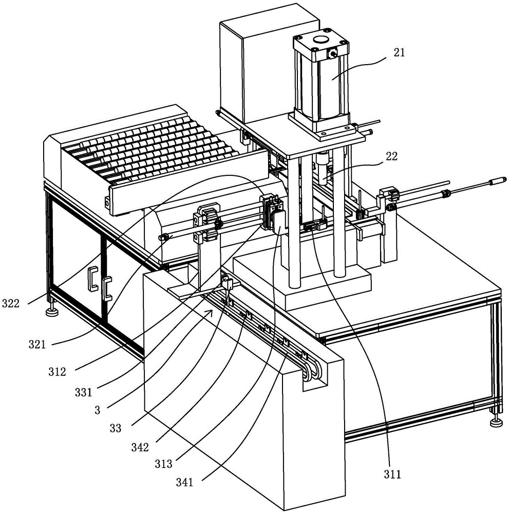
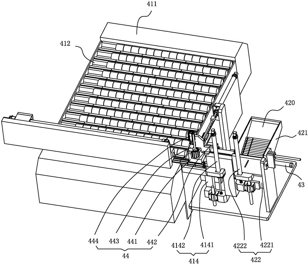
[0018] refer to Figure 1 to Figure 3 , a motor rotor shaft automatic assembly machine of the present invention includes a frame 1 provided with a press-fitting station, and an output device 3 for outputting the assembled motor rotor from the press-fitting station, on the press-fitting station A press-fitting mechanism 2 is provided, and the press-fitting mechanism 2 includes a press-fitting power unit 21 arranged on the frame 1, and a pressure head 22 driven by the pressing-fitting power unit 21 to move up and down. In order to prevent the rotor from tilting during the pressing down process, the pressing head 22 is provided with a positioning hole matched with the rotor. The frame 1 is provided with a pre-installation station on one side of the press-fitting station, and an automatic iron core supply warehouse 41 for transporting the horizontally placed iron core to the pre-installation station, and transporting the horizontally placed rotor shaft to the The rotor shaft auto...


PUM


Abstract

The invention discloses a motor rotor shaft automatic assembling machine, which comprises a machine frame and an output device, wherein the machine frame is provided with a press-fitting station; a press-fitting mechanism is arranged on the press-fitting station; the machine frame is provided with a pre-assembling station, an iron core automatic supply bin and a rotor shaft automatic supply bin on one side of the press-fitting station, the iron core automatic supply bin is used for conveying horizontally-placed iron cores to the pre-assembling station, and the rotor shaft automatic supply bin is used for conveying horizontally-placed rotor shafts to the pre-assembling station; the pre-assembling station is provided with an inserting and placing drive device and an overturning mechanism, the inserting and placing drive device is used for inserting the rotor shafts into the iron cores horizontally, and the overturning mechanism is used for overturning the iron cores inserted with the rotor shafts to be placed vertically; and an intermediate conveying mechanism which is used for conveying the iron cores inserted with the rotor shafts from the pre-assembling station to the press-fitting station is arranged on the machine frame. The motor rotor shaft automatic assembling machine can achieve the automatic assembly of the rotor shafts and the iron cores, greatly reduces labor intensity of workers, increases production efficiency, can effectively ensure the concentricity between the rotor shafts and the iron cores, prevents the iron cores from being damaged due to tilt rotor shafts because the rotor shafts are not inserted in place, and improves product quality.

Description

technical field [0001] The invention relates to the field of motor assembly equipment, in particular to an automatic motor rotor shaft assembly machine. Background technique [0002] Motors are widely used in household appliances, industrial and agricultural production, transportation and other fields. The motor rotor is an important component of the motor, which includes the rotor shaft and the iron core. The rotor shaft and the iron core are assembled by interference fit. The existing motor rotor The assembly is generally completed by semi-automation. First, the rotor shaft is manually inserted into the iron core, and then the iron core with the rotor shaft inserted is placed on the conveyor belt, which is transported to the press-fitting station through the conveyor belt. The mechanism presses the rotor shaft into the iron core to form an interference fit, and then the assembled motor rotor is output to the press-fitting station through the conveyor belt. This assembly m...

Claims


Application Information

Patent Timeline
Patent Type & Authority Applications(China)
IPC IPC(8): H02K15/02
Inventor 孙英华谭振豪郭小东
Owner 江门市智能装备制造研究院有限公司
Why Eureka
Try Eureka