Full-digital power factor correction circuit capable of carrying out switching frequency modulation

A technology of power factor correction and frequency switching, applied in the direction of sustainable manufacturing/processing, output power conversion devices, electrical components, etc., can solve the problems of PFC converters without power factor correction, etc., and achieve low THD and high power factor Effect

Inactive Publication Date: 2015-11-18
UNIV OF ELECTRONICS SCI & TECH OF CHINA
View PDF5 Cites 9 Cited by
  • Summary
  • Abstract
  • Description
  • Claims
  • Application Information

AI Technical Summary

Problems solved by technology

When the load continues to drop, the PFC converter will maintain DCM within a vin half-wa...

Method used


Image

  • Full-digital power factor correction circuit capable of carrying out switching frequency modulation
  • Full-digital power factor correction circuit capable of carrying out switching frequency modulation
  • Full-digital power factor correction circuit capable of carrying out switching frequency modulation

Examples


Embodiment Construction

[0020] Below in conjunction with accompanying drawing, describe technical scheme of the present invention in detail:

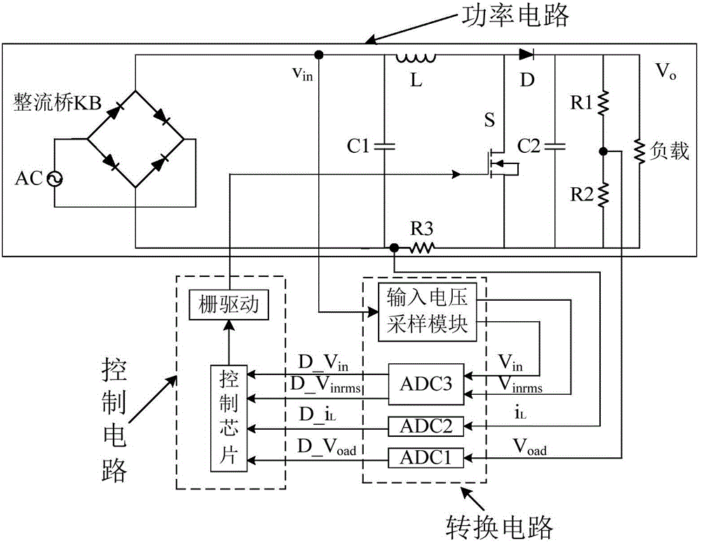
[0021] Such as figure 1 Shown, the all-digital single-cycle PFC scheme that has PWM with frequency switching modulation of the present invention includes Boost power converter, sampling / converting circuit and control circuit;

[0022] The Boost power converter is composed of a rectifier bridge KB, a filter capacitor C1, a power NMOS transistor S, a diode D, an inductor L, and an output capacitor C2; wherein, one end of L is input through the output terminal of the rectifier bridge KB and the filter capacitor C1 One end and the other end are connected to the drain of the power NMOS transistor S and the anode of the diode D; the source of the power NMOS transistor S is grounded, and the gate is controlled by the PWM signal output by the control module; one end of the output capacitor C2 is connected to the cathode of the diode D, and the other One end is ground...


PUM


Abstract

The invention belongs to the technical field of power electronics, and particularly relates to a full-digital power factor correction circuit capable of carrying out switching frequency modulation. According to the technical scheme, the full-digital power factor correction circuit comprises a Boost power converter, a sampling/converting circuit and a control circuit, wherein the control circuit comprises a voltage loop compensation module, a numerical calculation module, a current loop compensation module, a pulse-width modulation (PWM) module, a switching frequency modulation (SFM) module and a gate drive module. The full-digital power factor correction circuit has the beneficial effects that load current of the Boost converter can be monitored in real time without the need of a current sampling circuit; the switching frequency can be adjusted according to the load change condition; the condition that a power factor correction (PFC) converter keeps working in a continuous conduction mode (CCM) under the light-load condition can be ensured; and the PFC converter can obtain a high power factor and low total harmonic distortion (THD) under the full-load condition.

Description

technical field [0001] The invention belongs to the technical field of electronic circuits, and in particular relates to an all-digital power factor correction circuit capable of frequency switching modulation. Background technique [0002] The basic goal of the power factor corrector (PFC) is to ensure that the input current can maintain the same frequency and phase relationship with the input voltage, expressed as iL=vinGin by the formula. Among them, iL is the average current in a switching cycle Ts, vin is the rectified input voltage, and Gin is the input admittance. Simple structure and good dynamic characteristics make Boost topology the most common PFC topology. Many control methods about BoostPFC have been proposed, including the average current method, peak current method and hysteresis control method. Among them, the average current method has been widely used because of its advantages of precise control and good loop stability. The average current PFC control c...

Claims


Application Information

Patent Timeline
IPC IPC(8): H02M1/42
CPCY02B70/10Y02P80/10
Inventor 罗萍赖力邱双杰王康乐
Owner UNIV OF ELECTRONICS SCI & TECH OF CHINA
Why Eureka
Try Eureka