
Sensor device and method for detection of the surrounding environment of a vehicle

A technology for sensor devices and surrounding environments, applied in the direction of measurement devices, fluids using vibrations, piezoelectric/electrostrictive devices, etc.

Active Publication Date: 2018-12-14
ROBERT BOSCH GMBH
View PDF7 Cites 0 Cited by
  • Summary
  • Abstract
  • Description
  • Claims
  • Application Information

AI Technical Summary

Problems solved by technology

This means that additional assembly space is required and additional visible elements must be installed on the vehicle

Method used


Image

  • Sensor device and method for detection of the surrounding environment of a vehicle
  • Sensor device and method for detection of the surrounding environment of a vehicle
  • Sensor device and method for detection of the surrounding environment of a vehicle

Examples


Embodiment Construction

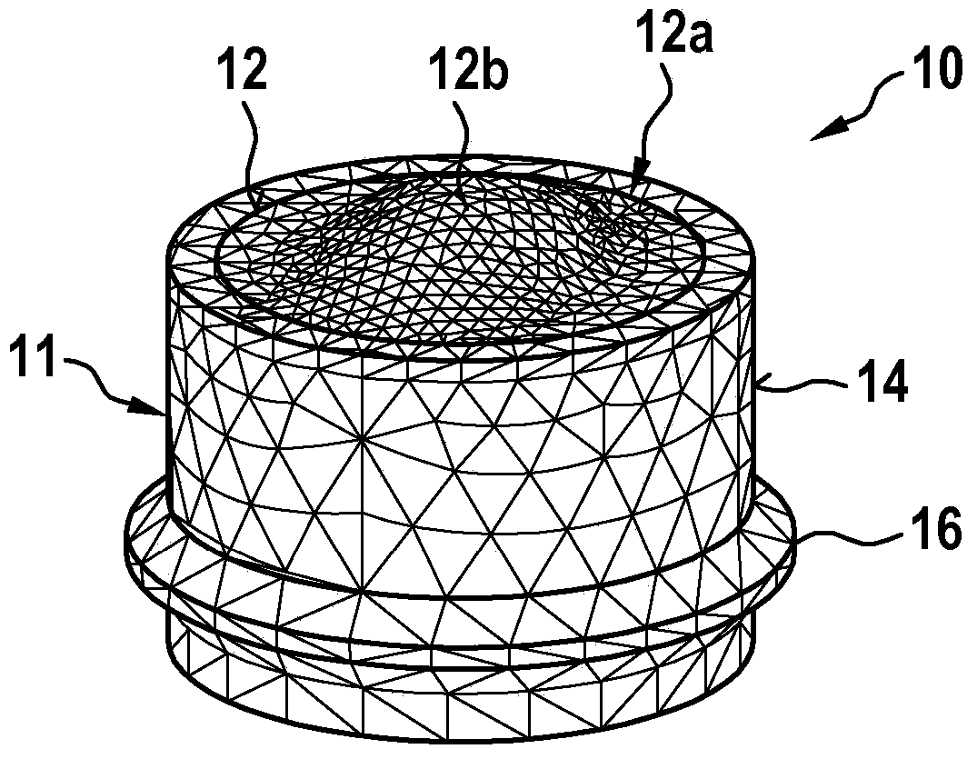
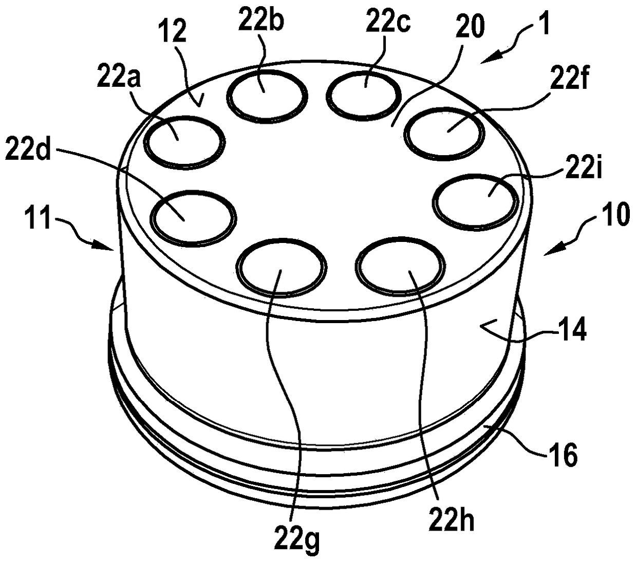
[0033] figure 1 An exemplary embodiment for the first sound transducer arrangement 10 is shown schematically in a perspective view. The first sound transducer device 10 comprises a pot-shaped element 11 which can be made of plastic or aluminium, for example. The element 11 comprises a bottom surface 12 designed as a diaphragm 12 and a surrounding edge surface 14 . The bottom surface 12 is substantially circular. Membrane 12 can, for example, be formed in one piece with element 11 or be fastened as a separate part to surrounding edge surface 14 . The edge surface 14 has a circumferential bead 16 in the direction of its edge facing away from the bottom surface 12 . This projection 16 is used to fasten the element 11 in a receptacle of a sensor housing (not shown), for example on a motor vehicle. A piezoelectric element (not shown) is arranged in a known manner on the diaphragm 12 in such a way that it excites the diaphragm 12 to vibrate, thereby enabling the emission of soun...


PUM


Abstract

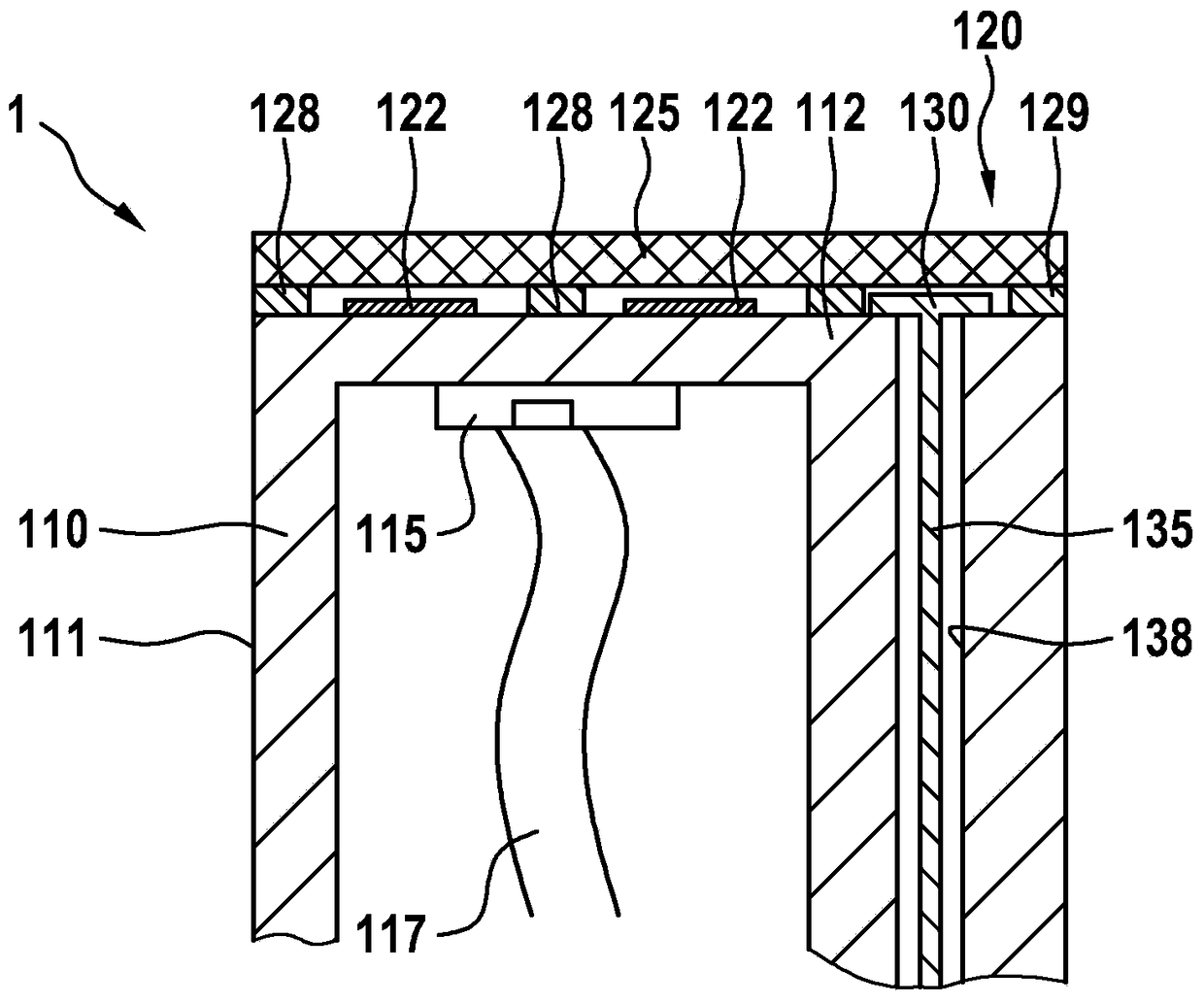
According to the invention, a sensor device (1) is proposed, which includes a first acoustic transducer device (10) having at least one surface configured as a diaphragm (12), wherein the diaphragm (12) is suitable for Emit ultrasonic waves. Such a sound transducer device (10) is also called a flexural vibration device and can generate sound waves with a relatively high sound pressure. The sensor device (1) according to the invention has a second acoustic transducer device (20) comprising a plurality of sensor elements (22a-22i) arranged in an array. It is proposed that the second sound transducer device (20) is arranged on a surface (12) of the first sound transducer device (10) configured as a diaphragm. According to the invention, the second acoustic transducer device (20) includes a sensor element (22a-22i) configured as an electret transducer element. Such a sensor device (1) may in particular be designed as an ultrasonic sensor device for detecting the surroundings of the vehicle.

Description

Background technique [0001] Ultrasonic sensors (USS) are used today, for example, to support the driver of the vehicle during parking. Here, the USS acts as a transmitter and receiver at the same time. The transmitted ultrasound signal is reflected by the object. The distance to the object is then determined by a travel time calculation. The lateral position of the object is determined by means of triangulation. [0002] Known ultrasonic sensors generally have piezoelectric elements which are connected to the diaphragm of the ultrasonic sensor. By correspondingly actuating the piezoelectric element, the diaphragm of the ultrasonic sensor can be vibrated in order to emit an acoustic signal. In order to receive the reflected signal, the vibration of the diaphragm is converted into a corresponding voltage signal by the piezoelectric element. [0003] In the context of object distance calculations by means of triangulation, inaccuracies in determining the angle of incidence o...

Claims


Application Information

Patent Timeline
Patent Type & Authority Patents(China)
IPC IPC(8): B06B1/02G01S15/93G01S15/04H01L41/31H04R19/01H10N30/07
CPCB06B1/0292H04R19/01G01S7/521G01S2015/932H04R2499/13
Inventor D·巴尔特伊拉T·特肋普托D·施密德M·舒曼
Owner ROBERT BOSCH GMBH
Learn More