Cable retaining apparatus

A clamping device and cable technology, applied in the direction of pipe supports, electrical components, pipes/pipe joints/fittings, etc., can solve problems such as cable sheath damage, prevent damage, reduce the possibility of damage, reduce The effect of the possibility of bending

Active Publication Date: 2015-11-18
CMP PRODS
View PDF6 Cites 8 Cited by
  • Summary
  • Abstract
  • Description
  • Claims
  • Application Information

AI Technical Summary

Problems solved by technology

Although the clamp is usually strong enough to hold the cable in place, this movement creates additional space within the clamp to allow the cable to move
This causes the components of the clamp, including the threaded portion of the now bent bolt, to cause damage to the outermost jacket of the cable

Method used


Image

  • Cable retaining apparatus
  • Cable retaining apparatus
  • Cable retaining apparatus

Examples


Embodiment Construction

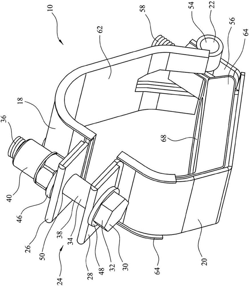
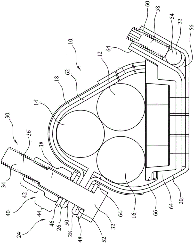
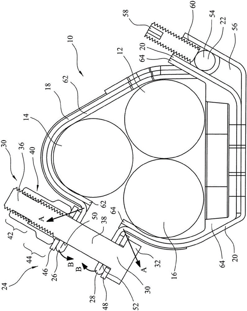
[0044] see Figure 1 to Figure 3 , the present invention provides a cable clamping device in the form of a cable clamp 10 for clamping at least one cable, three cables are shown in the example, cables 12, 14 and 16 respectively. The cable clamp 10 includes a first cable gripping assembly 18 which engages the cables 12 and 14 in use. The cable clamp 10 also includes a second cable clamping assembly 20 that contacts the cable 12 and the other cable 16 . exist Figures 1 to 3In the illustrated embodiment, the first and second cable gripping assemblies 18 and 20 are obtained by bending and welding steel plates into the shapes shown in these figures. The first and second cable gripping assemblies 18 and 20 are hingedly connected to each other by a pivot in the form of a hinge 22 .

[0045] The cable clamp 10 further includes a clamping portion generally indicated at 24 . The clamping portion 24 includes a first flange 26 mounted on and in the embodiment forming part of the firs...


PUM


Abstract

A cable retaining apparatus, or trefoil cleat, for retaining three cable high voltage cables is disclosed. Two halves of the cleat are hinged together and between them engage the three cables. There is also a clamping portion for pulling the two halves together which includes a clamping member at the non-hinged end of each half. Both clamping members have holes through them and one hole has an internal thread. There is also a bolt that extends through the non-threaded hole and into the threaded hole. The bolt has a non-threaded portion that extends at least between the clamping members when the cleat is in use.

Description

technical field [0001] The invention relates to a cable clamping device, in particular to but not limited to a clamp for clamping three sheathed power cables used in three-phase power distribution. Background technique [0002] In three-phase power transmission, if a three-phase short circuit occurs between any cables, the electromechanical force developed between the cables causes a sudden and violent movement of the cables in the opposite direction. This is very dangerous for the voltage on the distribution cable and can cause personal injury and damage to the cable and surrounding equipment. [0003] Therefore, a cable clamp (also known as a three-leaf clamp) is currently used to clamp the three cables together. This is especially the case where the cables are mounted on a wall, floor or other surface and the cable wires are held together with evenly spaced, strong clamps in case of a three-phase short circuit. An example of such a cord clamp in the prior art has a tria...

Claims


Application Information

Patent Timeline
Patent Type & Authority Applications(China)
IPC IPC(8): H02G3/32F16L3/10
CPCH02G3/32F16L3/1075F16L3/23H02G3/0456
Inventor 李·弗里泽尔
Owner CMP PRODS
Why Eureka
Try Eureka