
A circulating energy-saving and water-saving fast steamer

A circulation type, steamer technology, applied in the field of steamer, can solve the problems of large environmental impact, heat loss, poor steam cycle effect, etc., to achieve the effect of eliminating steam escape, accelerating heating speed, and reducing heat energy loss

Active Publication Date: 2017-03-22
浙江甬源塑业有限公司
View PDF7 Cites 0 Cited by
  • Summary
  • Abstract
  • Description
  • Claims
  • Application Information

AI Technical Summary

Problems solved by technology

After the steam comes out of the steamer, it will be emitted into the air, which is undoubtedly a loss of heat and a waste of resources, and it also affects the heating efficiency of the steamer.
[0003] In the prior art, there is also a drawer-type steamer structure. When the drawer is opened and the steamed product is taken out, a large amount of steam leakage will occur; since the steam passes through the drawer-type steamer from bottom to top, it is often caused by uneven heating up and down. In addition, the circulation effect of steam is poor, resulting in the loss of heat and waste of resources, and has a great impact on the environment

Method used


Image

  • A circulating energy-saving and water-saving fast steamer
  • A circulating energy-saving and water-saving fast steamer
  • A circulating energy-saving and water-saving fast steamer

Examples


Embodiment Construction

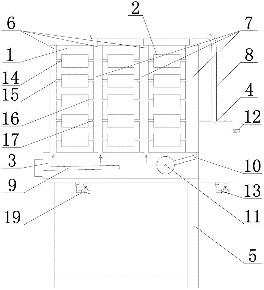
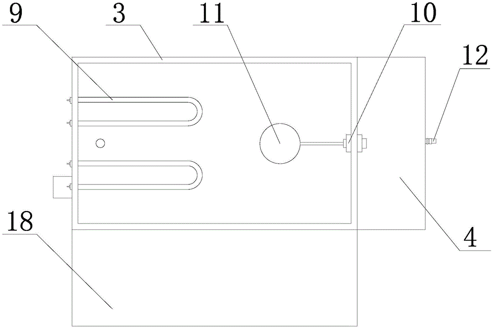
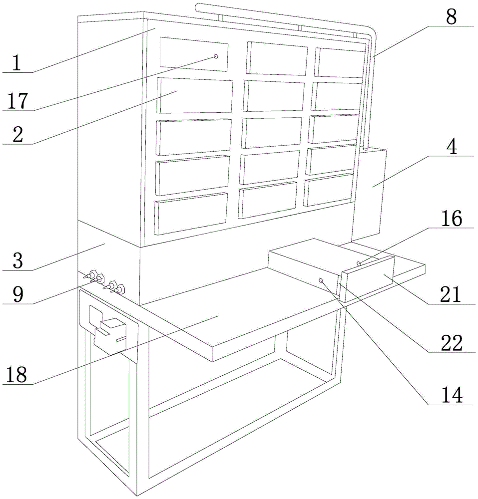
[0028] Figures 1 to 3 Among them, a circulating energy-saving and water-saving fast steamer includes a steaming rack 5, a steaming box 1, a water tank 3 and a heating device, the heating device provides a heat source for the water in the water tank, the heating device is an electric heating device 9, and the electric heating device 9 The electric heating tube is located in the water tank 3, and provides heating for the water in the water tank through the electric heating tube. The electric heating device 9 is fixed on the steamer 1 with screws through the flange and the protective shell, and the steamer 1 is provided with a switch and a protection device. The electric heating device 9 is provided with a connection terminal, and is connected with a temperature controller, and the output temperature and closing of the electric heating tube are set as required. The water tank 3 is located above and below the steaming rack 5, and one side of the water tank 3 is provided with a re...


PUM


Abstract

The invention discloses a circulating energy-saving and water-saving rapid steamer, which comprises a steaming shelf, a water tank and a heating device, wherein a water refilling tank is arranged on one side of the water tank; an automatic water refilling valve is arranged between the water refilling tank and the water tank; a steaming box is arranged on the water tank; steamer drawers which are longitudinally distributed are arranged on the steaming box; the part, on one side of each drawer, of the steaming box is provided with an air inlet cavity, and the part, on the other side of each drawer, of the steaming box is provided with an air outlet cavity; the lower parts of the air inlet cavities are communicated with the interior of the water tank; the upper parts of the air outlet cavities are connected to an air outlet pipeline, and the air outlet pipeline is connected to the water refilling tank; air inlet holes are formed in side plates on the air inlet sides of the drawers; vent holes which are communicated with the air inlet holes are formed in side plates corresponding to the air inlet cavities when all drawers are pushed into the steaming box; air outlet holes are formed in the side plates on the air outlet sides of the drawers; and air guide holes which are communicated with the air outlet holes are formed in side plates corresponding to the air outlet cavities when all drawers are pushed into the steaming box. The rapid steamer disclosed by the invention can be used for effectively eliminating the problems of steam escape, heat energy loss and energy waste, and the rapid steamer can effectively recover steam and recycle energy so as to achieve purposes of saving energy and saving water; and meanwhile, the rapid steamer has a small influence on environment.

Description

technical field [0001] The invention relates to a steamer, in particular to a circulating energy-saving and water-saving steamer. Background technique [0002] The steamer is a wonderful flower of oriental food. The steamer is famous all over the world because of its original taste, the steam water does not flow back, and the color, fragrance and taste are complete. The effect of steamer is various, can steam steamed stuffed bun, siu mai, rice cake, also can steam fish head, chicken and duck etc., the food that steamer is made is not only delicious but also healthy, has obtained extensive liking of broad masses of people. We traditionally use steamers, usually layer upon layer of steamers are placed on the boiling water pot, and the food in the steamer is steamed by heating water to generate water vapor. After the steam comes out of the steamer, it will be emitted into the air, which is undoubtedly a loss of heat and a waste of resources, and also affects the heating effici...

Claims


Application Information

Patent Timeline
Patent Type & Authority Patents(China)
IPC IPC(8): A47J27/04A47J36/00
Inventor 郑军华郑合根
Owner 浙江甬源塑业有限公司
Learn More