Hose lines for fresh and/or used dialysate

A dialysate and hose technology, used in dialysis systems, drug devices, other medical devices, etc., can solve the problems of high temperature loss of hot water, lack of weight errors, and inability to ensure, to reduce temperature loss and quality changes. Reduce and realize the effect of quality change

Active Publication Date: 2019-12-13
B BRAUN AVITUM
View PDF7 Cites 0 Cited by
  • Summary
  • Abstract
  • Description
  • Claims
  • Application Information

AI Technical Summary

Problems solved by technology

Compensation of the resulting temperature losses is however not possible since the losses along the hose line are not known more precisely
Furthermore, the temperature loss of the hot water during the disinfection operation may be too high, so that the necessary temperature for disinfection, for example 83° C., cannot be ensured throughout the disinfection process.
Additional energy consumption is generated by the required reheating to compensate for the heat loss to the environment
Finally there is a risk of burning in contact during disinfection without isolation
[0011] On the other hand, the temperature of the dialysate at the dialyzer inlet can be undesirably too high at high and thus heated ambient temperatures of the dialysate
[0012] In addition, temperature fluctuations of the dialysate disadvantageously lead to quality changes of the dialysate which, due to volumetric deficits of the dialysis machine, lead to missing errors or missing deviations in weight

Method used


Image

  • Hose lines for fresh and/or used dialysate
  • Hose lines for fresh and/or used dialysate
  • Hose lines for fresh and/or used dialysate

Examples


Embodiment Construction

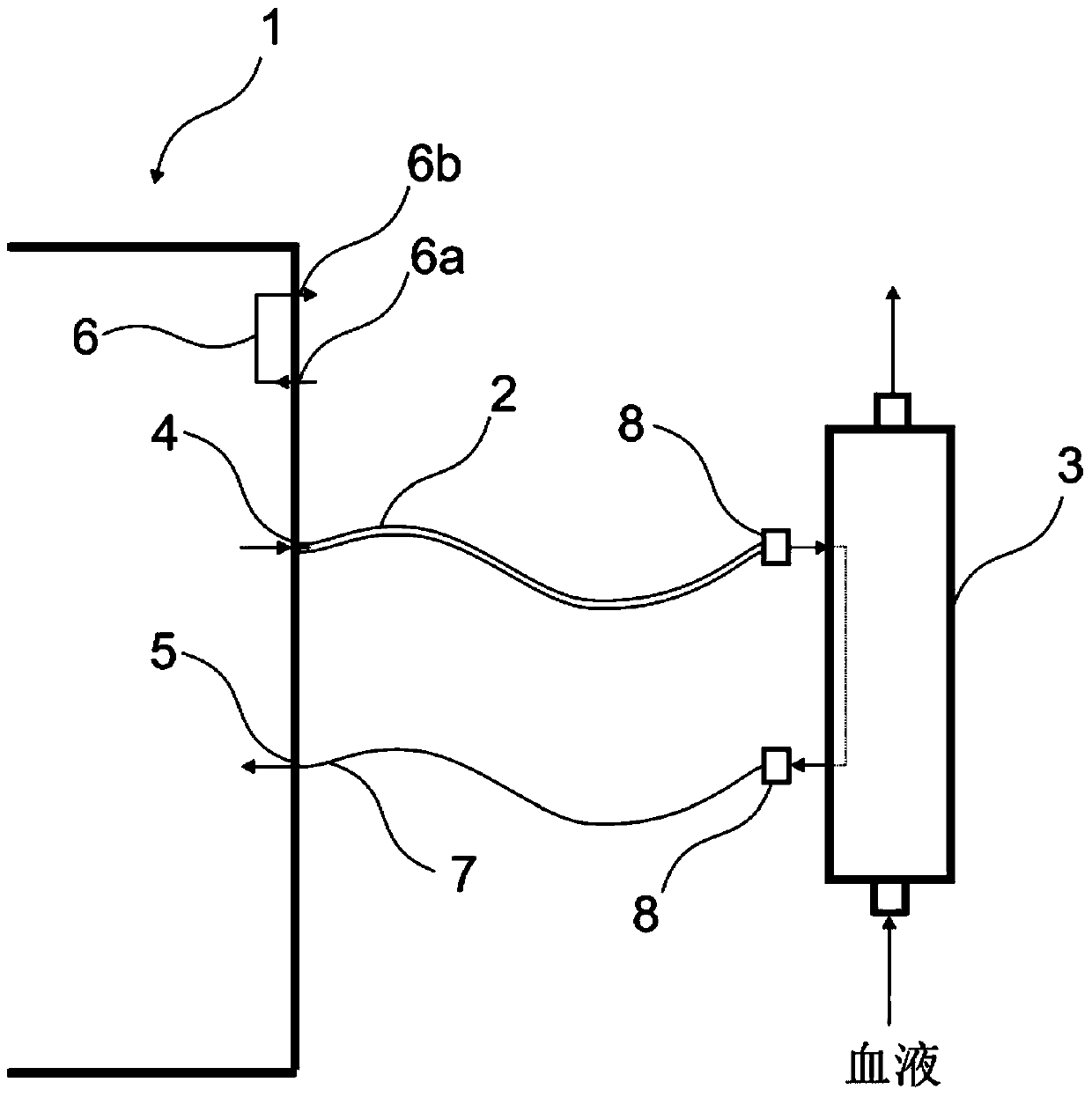
[0064] figure 1 Shown is a simplified view of a dialysis machine 1 via a first hose line (hose supply line) 2 for fresh dialysate and a second hose line for used dialysate according to one embodiment. Two hose lines (hose outlet lines) 7 are connected to the dialyzer 3 .

[0065] Dialysis machine 1 in figure 1 marked on the left. Dialysis devices or dialysis machines are known per se, so details of the dialysis machine 1 , such as internal components which are not directly related to the dialysate hose lines 2 , 7 , are not shown for reasons of clarity.

[0066] In the described example already as in figure 1 As shown in the dialysis machine 1, there is in particular a dialysate outlet 4, which represents the flow direction from fresh dialysate to a dialyzer 3 arranged outside the dialyser 1; a dialysate inlet 5, which provides Outflow of used dialysate from dialyzer 3; cleaning bridge 6, with an inlet 6a and an outlet 6b each for cleaning fluid, through which first hose l...


PUM


Abstract

Provided is a hose line for fresh and / or consumed dialysis fluid. It is proposed a dialysis fluid tubing for producing a fluid connection between a dialysis fluid outlet on a dialysis machine and a dialysis fluid input to a dialyzer and / or establish a fluid connection between a dialysis fluid outlet to the dialyzer and a dialysate input to the dialysis machine with at least one designed for the passage of dialysis fluid lumen of a predetermined cross-section and / or diameter, wherein the at least one lumen is arranged to provide a dialysis fluid so that a loss of temperature of the dialysis fluid path between bounded along the dialysis machine and dialyzer and a predetermined temperature accuracy of the dialysis fluid is obtained at least in the dialysis fluid inlet of the dialyzer. In one embodiment, the at least one lumen is split into at least two lumens same or different cross section and / or diameter, wherein the at least two lumens individually when subjected to dialysis liquid from a inlet side external device on the dialysis machine or can be applied in a parallel manner with a dialysis fluid, and the output side open into a single lumen at the dialyzer.

Description

technical field [0001] The invention relates to a hose connection for use in the field of blood cleaning, and preferably to a hose for conveying dialysate when using a dialysis machine. Background technique [0002] In almost all dialysis machines on the market today, hose lines or hoses are used on their outlet and / or inlet or on the corresponding inlet or outlet for the dialysate, which have so-called Hansen connectors for connection to dialyzer. During a treatment procedure the dialyzer is connected to the dialysis machine and the dialysate flows through the housing of the dialyzer while the blood to be cleaned flows in countercurrent through the hollow fibers in the interior of the dialyzer. [0003] For example, during the sterilization process the hose lines are short-circuited while detached from the dialyzer, for which purpose the hose lines are usually coupled to the dialysis machine in such a way that the two lines are connected internally. In addition, so-called...

Claims


Application Information

Patent Timeline
Patent Type & Authority Patents(China)
IPC IPC(8): A61M1/18A61M1/22
CPCA61M1/1631A61M1/1633A61M1/16A61M1/1694A61M2039/082A61M2205/3331A61M2205/3368A61M2205/3633A61M2206/10A61M2206/18A61M2206/20
Inventor 卡伊尤韦·里特尔
Owner B BRAUN AVITUM
Why Eureka
Try Eureka