Sawing machine and sawing machine control method

A control method and technology of a machine control device, which are applied in shearing machine control devices, automatic control devices, manufacturing tools, etc., can solve the problems that sensors cannot be successfully realized, and achieve the effect of shortening time.

Active Publication Date: 2017-11-28
KEURO BESITZ & EDV DIENSTLEISTUNGS
View PDF7 Cites 0 Cited by
  • Summary
  • Abstract
  • Description
  • Claims
  • Application Information

AI Technical Summary

Problems solved by technology

But in this type of saw machine there are severe conditions in the cutting area or in the area of ​​the saw table, so the use of sensors is always problematic and usually not possible smoothly

Method used


Image

  • Sawing machine and sawing machine control method
  • Sawing machine and sawing machine control method
  • Sawing machine and sawing machine control method

Examples


Embodiment Construction

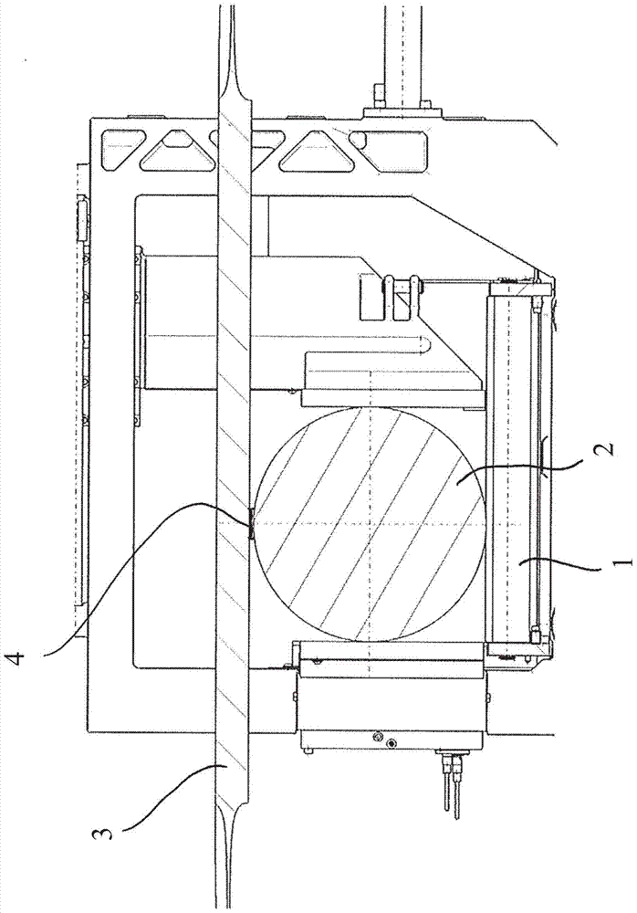
[0034] figure 1 A saw table 1 of a band saw machine is schematically shown, on which a workpiece 2 (here a cylindrical strip) is placed. Above the workpiece, the saw band 3 as a saw blade circulates around two deflection rollers (not shown) in the upper part of an elevating saw machine. The saw band moves from right to left within the drawing in the selected view.

[0035] Such as figure 1 The moment shown is the start of the actual cutting process: the saw band 3 moves downwards during the feed movement in the cutting plane which coincides with the drawing plane in the selected view and moreover comes into contact with the workpiece 2 . In the joining section 4 , the saw band 3 cuts into the material of the workpiece 2 and cuts through the workpiece by the cutting action of the saw teeth arranged on the lower end of the saw band 3 .

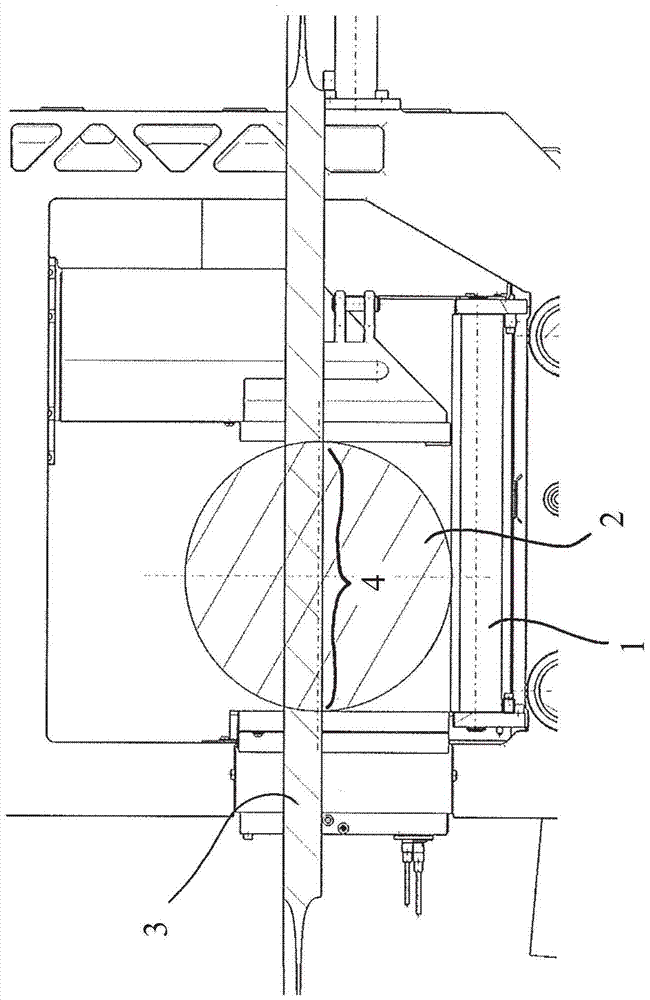
[0036] figure 2 A later moment in the cutting process is shown. Here, the saw band 3 is located approximately in the center of the cross-...


PUM


Abstract

The invention relates to a saw machine control method. The saw machine comprises a saw blade driven by an electric saw blade drive with a frequency converter and a sawing feed for moving the driven saw blade with a variable feed speed relative to a workpiece to be sawed by means of the electric feed drive to the device. For the first cut in the workpiece, a constant or variable machining feed rate specific to the workpiece geometry, workpiece material and saw blade is predetermined. An instantaneous value of a physical variable is determined on the frequency converter, which is related to the torque transmitted by the saw drive to the saw blade, and is transmitted as an instantaneous torque value to the machine control. The momentary torque values ​​are continuously evaluated, where the maximum torque value for the first cut is ascertained and based on this the maximum value of the torque value is determined. For all subsequent cuts in the same workpiece, the machining feed rate is adjusted using the momentary torque value as control variable such that the momentary torque value remains constant and as close as possible to the maximum value.

Description

technical field [0001] The invention relates to a saw machine control method and a saw machine. Such a saw machine is also used in the method and includes a saw blade, which is driven by an electric saw blade drive with a frequency converter. In addition, a saw feed device is provided which moves the saw blade relative to the workpiece to be sawed at a variable feed speed by means of an electric feed drive. Finally, the saw machine also includes a machine control. Background technique [0002] Saws of this type are usually constructed in the form of band saws or circular saws, occasionally also in the form of hacksaws. The main field of application of the invention is the cutting or sawing of metal workpieces. [0003] Depending on the type of saw machine, the driven saw blade (ie generally the saw band or circular saw blade) is moved relative to the workpiece linearly or about a rotary axis. The workpiece is heavy and is usually placed on the saw table by means of a tra...

Claims


Application Information

Patent Timeline
Patent Type & Authority Patents(China)
IPC IPC(8): B23D36/00B23Q15/12B23D55/08B23D47/08B23Q17/20
CPCB23D59/001Y10T83/0524Y10T83/141B23D55/046B23D55/088Y10T83/04B23D53/08
Inventor A·施托尔策马库斯·奥伯尔
Owner KEURO BESITZ & EDV DIENSTLEISTUNGS
Why Eureka
Try Eureka