Magnetic control device for resistance spot welding with adjustable position

A technology of resistance spot welding and magnetron device, applied in resistance welding equipment, welding equipment, transportation and packaging, etc., can solve the problems of difficult adjustment of working distance of magnetron device, reduced automobile production rhythm, fragile permanent magnet, etc. To achieve the effect of easy replacement, convenient operation and enhanced stirring effect

Active Publication Date: 2017-05-24
SHANGHAI JIAOTONG UNIV
View PDF7 Cites 0 Cited by
  • Summary
  • Abstract
  • Description
  • Claims
  • Application Information

AI Technical Summary

Problems solved by technology

During grinding, it is necessary to remove the magnetic control device, and then install it back after grinding, resulting in a decrease in the production cycle of the car
[0005] 2) It is difficult to adjust the working distance of the magnetic control device
The adjustment of the working distance requires dismantling the entire magnetic control system, which is inefficient and poor in accuracy.
[0006] The above method uses an interference fit to fix the permanent magnet, which is easily broken during the assembly process

Method used


Image

  • Magnetic control device for resistance spot welding with adjustable position
  • Magnetic control device for resistance spot welding with adjustable position
  • Magnetic control device for resistance spot welding with adjustable position

Examples


Embodiment 1

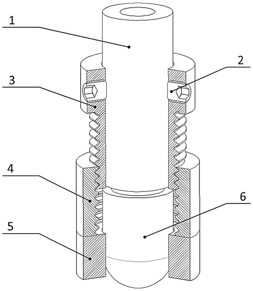
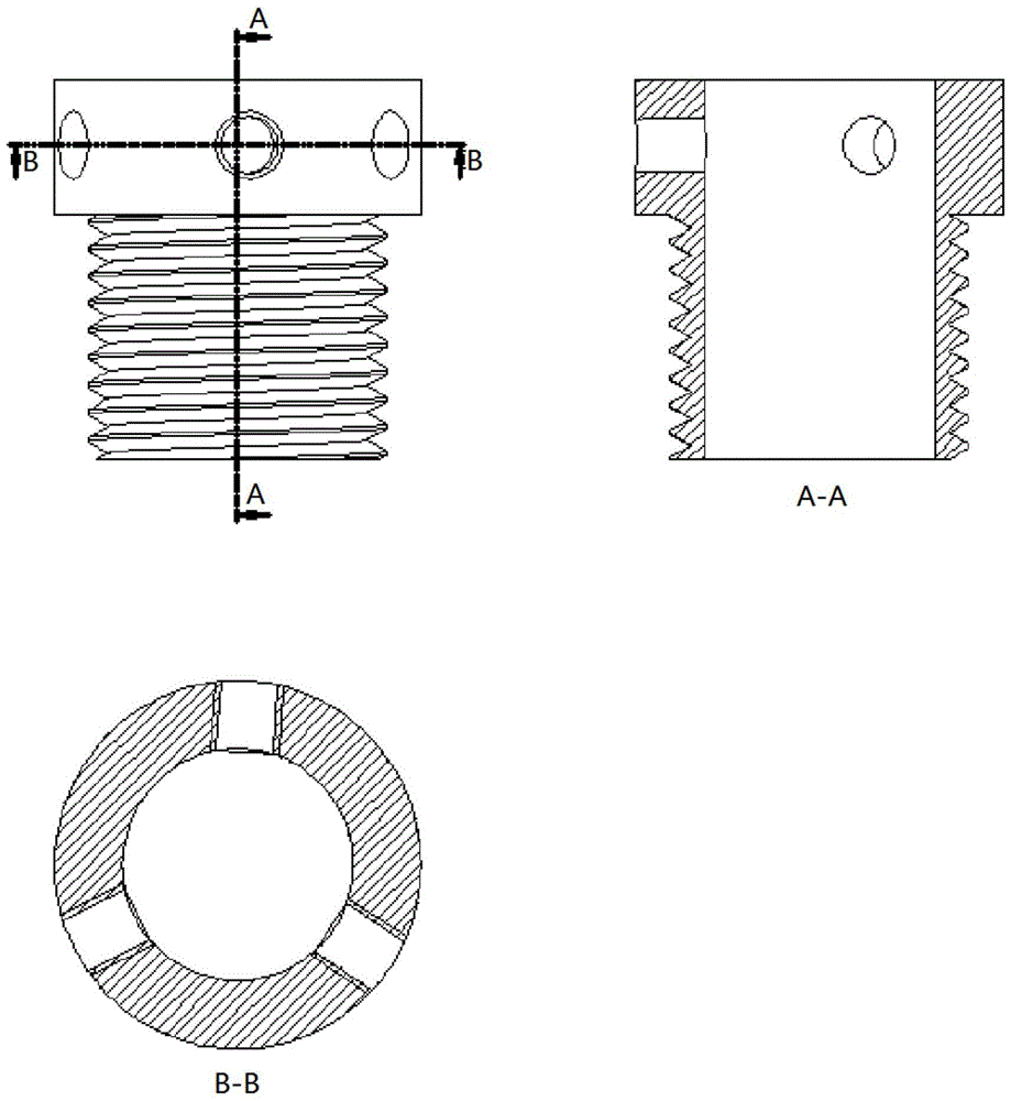
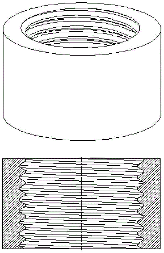
[0038] like Figure 5 As shown, this embodiment includes: electrode rod 1, positioning screw 2, bushing 3, positioning guide sleeve 4, annular permanent magnet 5, electrode cap 6, plate 7 and electrode dresser 8, wherein: bushing 3 and electrode The rod 1 is fixedly connected by a positioning screw, the positioning guide sleeve 4 is movably socketed with the bushing 3, the annular permanent magnet 5 is fixedly connected with the positioning guide sleeve 4, and the electrode cap 6 is connected with the electrode rod 1.

[0039] The magnetization direction of the annular permanent magnet 5 is parallel to its axis of symmetry, and its magnetic field distribution is axisymmetric.

[0040] The number of the ring-shaped permanent magnets 5 is 1 pair, and the polarities are mutually exclusive, so as to realize double-sided stirring.

[0041] The annular permanent magnet 5 has an inner diameter 0.5mm larger than the outer diameter of the electrode rod, a wall thickness of 5mm, and a ...


PUM

PropertyMeasurementUnit
thicknessaaaaaaaaaa
heightaaaaaaaaaa
thicknessaaaaaaaaaa

Abstract

The invention discloses a position-adjustable resistance spot welding magnetic control device. The position-adjustable resistance spot welding magnetic control device comprises a positioning guide sleeve, an annular permanent magnet fixedly connected with the positioning guide sleeve through ferromagnetic attraction force, a lining, an electrode stem, an electrode cap and positioning screws, wherein the lining is fixedly connected with the electrode stem through the positioning screws, the positioning guide sleeve is movably connected with the lining in a sleeving manner, the annular permanent magnet is fixedly connected with the positioning guide sleeve, and the electrode cap is connected with the electrode stem. The position-adjustable resistance spot welding magnetic control device has the beneficial effects that the magnetic control system has a grinding stop position, so that interference between the permanent magnet and a grinding tool is avoided; thread adjustment of the working position of the permanent magnet can be performed as needed, so that precision is high, and operation is convenient; the permanent magnet is connected with the end face of the positioning guide sleeve through ferromagnetic attraction force, so that replacement is easy, and process flexibility is high; and the inner diameter of the permanent is further reduced, so that the magnetic field intensity of a welding nuclear area is improved, and the stirring effect is enhanced.

Description

technical field [0001] The invention relates to a technology in the field of metal welding, in particular to a position-adjustable resistance spot welding magnetron device. Background technique [0002] Body weight reduction is the development trend of today's automobiles, and the extensive application of new materials such as high-strength steel / ultra-high-strength steel is an important means of weight reduction. However, this brings new challenges to the traditional resistance spot welding process. The high heat input and extremely fast cooling rate of resistance spot welding can easily lead to the formation of a large number of hardened and directional brittle structures inside the nugget, which makes the spot welded joint more prone to interface fracture and failure under external load. This not only significantly reduces the static load strength of solder joints, weakens the impact resistance and energy absorption effect of joints, but also shortens the fatigue life of...

Claims


Application Information

Patent Timeline
Patent Type & Authority Patents(China)
IPC IPC(8): B23K11/11B23K11/36
CPCB23K11/11B23K11/36B23K2101/006
Inventor 李永兵李定泷楼铭林忠钦
Owner SHANGHAI JIAOTONG UNIV
Why Eureka
Try Eureka