Method and system for laser cutting through dynamic following of synchronous passing plates

A laser cutting and laser cutting head technology, applied in laser welding equipment, welding/cutting auxiliary equipment, welding equipment, etc., can solve the problems of lower production efficiency, automatic removal of difficult-to-shape waste, and stable knife breaking in difficult-to-cut processes, etc., to achieve The effect of improving work efficiency

Active Publication Date: 2015-11-25
BAOSHAN IRON & STEEL CO LTD
View PDF6 Cites 17 Cited by
  • Summary
  • Abstract
  • Description
  • Claims
  • Application Information

AI Technical Summary

Problems solved by technology

[0004] However, the common feature of these modes is that during the cutting process, the support conveyor can be stationary or extended or retracted according to the contour shape requirements. During the cutting process, the support conveyor belt is in a fixed static position. The disadvantage of this mode of operation It is difficult to ensure the stable breaking of the cutting process, and it is difficult to realize the automatic removal of special-shaped waste, which reduces the production efficiency

Method used


Image

  • Method and system for laser cutting through dynamic following of synchronous passing plates
  • Method and system for laser cutting through dynamic following of synchronous passing plates
  • Method and system for laser cutting through dynamic following of synchronous passing plates

Examples


Embodiment Construction

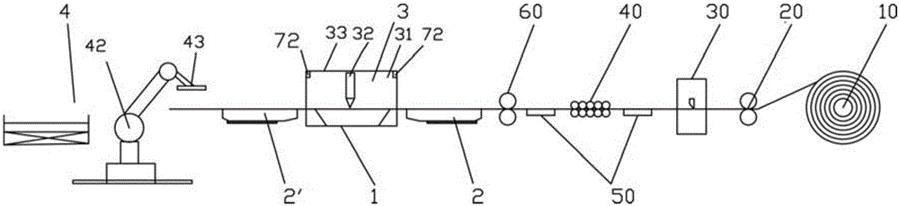
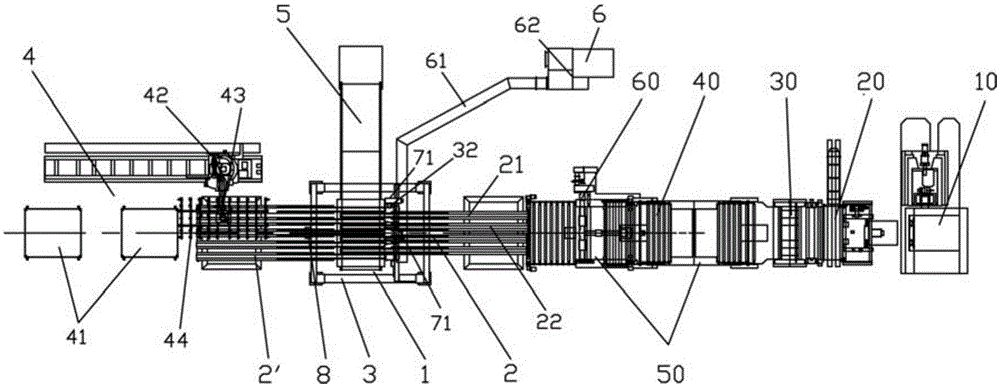
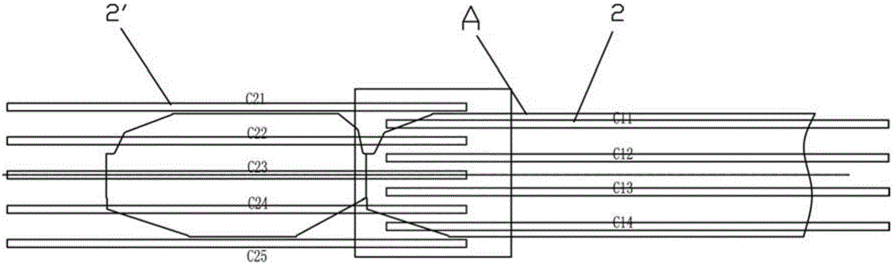
[0034] see figure 1 , figure 2 , the system of synchronous plate-passing dynamic follow laser cutting of the present invention, it comprises: a processing position 1; On the material side, each magnetic belt C11, C12, C13, C14, C21, C22, C23, C24, C25 in the magnetic belt group can be extended or retracted, and the gap between each magnetic belt can be adjusted;

[0035] The laser cutting unit 3 is arranged on the processing position 1, and it includes at least one laser cutting machine 31 and an upper laser cutting head 32;

[0036] The handling and stacking unit 4 includes a stacking platform 41 and a handling and stacking robot 42 (end picker 43 and its vacuum chuck 44), and the stacking platform 41 is arranged on the synchronous pass-through unit 2' on the discharge side of the processing position 1 Magnetic belt set outside;

[0037] The waste conveyor belt device 5 is arranged on the side perpendicular to the feeding direction of the processing position 1;

[0038] ...


PUM

PropertyMeasurementUnit
lengthaaaaaaaaaa

Abstract

The invention discloses a method and system for laser cutting through dynamic following of synchronous passing plates. The system comprises one or more machining positions, a synchronous passing plate unit, a laser cutting unit, a carrying stacking unit, a waste conveyor belt device, a smoke treatment device, a real-time measuring device for strip steel cutting, a position detection device and a cutting control system, wherein magnetic belt sets are adopted in the synchronous passing plate unit and arranged on the feeding side and the discharging side of each machining position respectively, magnetic belts can stretch and retract, and the belt intervals are adjustable; the laser cutting unit is arranged at each machining position and comprises at least one laser cutting machine and a laser cutting head; the carrying stacking unit comprises a stacking table and a stacking robot, and the stacking table is arranged on the outer side of the magnetic belt set on the discharging side of each machining position; the waste conveyor belt device is arranged on the side, perpendicular to the feeding direction, of each machining position; the smoke treatment device and the real-time measuring device for strip steel cutting are arranged at each machining position; the position detection device in front of sheet stacks is arranged at the carrying position of the magnetic belt set on the discharging side; and the cutting control system controls all the units, and the magnetic belts stretch or retract to follow the laser cutting head. Dynamic following of the magnetic belt sets can be achieved in the cutting process, so that the machining tact time is shortened, and the yield is further improved.

Description

technical field [0001] The invention relates to the field of steel strip processing, in particular to a method and a system for synchronously passing a plate and dynamically following laser cutting used in the technical field of automobile manufacturing. Background technique [0002] Based on laser technology, it is a mature commercial technology in the field of material cutting and processing, and the laser numerical control processing system for incoming metal rectangular plates has been widely used. With the vigorous development of laser technology, it has also brought faster speed and more flexible application methods to sheet metal processing. At the same time, it has also created a demand for automated loading and unloading and high-paced continuous production. At the same time, the uncoiling laser cutting processing of coiled materials has also been studied and gradually applied. For example, Chinese patent CN102281986A discloses a conveyor system for laser cutting pr...

Claims


Application Information

Patent Timeline
Patent Type & Authority Applications(China)
IPC IPC(8): B23K26/38B23K26/70
CPCB23K26/38B23K26/16B23K2101/16B23K26/702B23K2101/006B23K26/0846B23K26/0853B23K37/0288B23K37/0408
Inventor 吴瑞珉杨赛丹梁兆东丁烨
Owner BAOSHAN IRON & STEEL CO LTD
Why Eureka
Try Eureka