Slip casting mechanism

A technology of grouting molding and molding cavity, which is used in ceramic molding machines, die-casting molds, manufacturing tools, etc., can solve the problems of large gaps, leakage, and poor ceramic molding effect at the junction of punches and punches. leakage effect

Inactive Publication Date: 2015-11-25
CHONGQING XINSHENG CERAMICS
View PDF0 Cites 0 Cited by
  • Summary
  • Abstract
  • Description
  • Claims
  • Application Information

AI Technical Summary

Problems solved by technology

[0004] The existing grouting molding mechanism includes a plaster mold and a mud pump. The plaster mold includes a punch and a die assembled by bolts. A cavity is formed between the punch and the die. The cavity is connected with the mud pump through a pipeline. The disadvantages of the slurry molding machine are: ①The contacting edge of the punch and the die is flat, and after the mud enters the cavity, it is easy to leak from the edge of the punch and the die, resulting in poor ceramic molding effect; ②The existing punch Both the mold and the die are connected with bolts. After a long time of use, the bolts are rusted and aged, resulting in a large gap at the junction of the punch and the punch, resulting in mud leaking from the edge of the punch and the die.

Method used


Image

  • Slip casting mechanism
  • Slip casting mechanism

Examples


Embodiment Construction

[0013] The present invention is described in further detail below by specific embodiments:

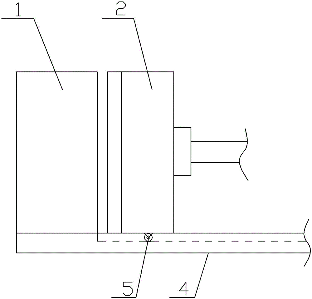
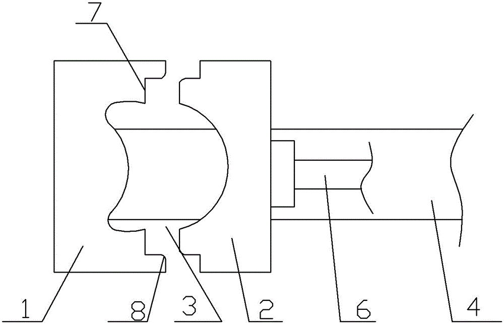
[0014] The reference signs in the accompanying drawings of the description include: punch 1, die 2, mud forming cavity 3, guide groove 4, roller 5, cylinder output shaft 6, right-angle fold line structure 7, guide angle 8.

[0015] The embodiment grouting molding mechanism is basically as attached figure 1 shown:

[0016] The grouting molding mechanism includes a punch 1 and a die 2.

[0017] The middle part of the male mold 1 is a protrusion, and the middle part of the concave mold 2 is a groove. After the convex surface is matched with the concave mold 2, a mud molding cavity 3 with the same shape and size as the target ceramic product is formed between the protrusion and the groove. A pipeline is opened on the punch 1, and the pipeline communicates with the mud forming cavity 3, and the pipeline is externally connected with a mud pump.

[0018] like figure 1 As shown, the bottom...


PUM


Abstract

The invention belongs to the technical field of slip casting of ceramic products, and provides a slip casting mechanism. The slip casting mechanism comprises a male die and a female die. The male die and the female die form a sludge molding cavity after being combined. A slip casting opening led to a cavity is formed in the male die or the female die. The female die or the male die is fixedly connected to the end of a guide groove below the female die or the male die, and the corresponding male die or female die is in sliding fit with the guide groove and is driven by an air cylinder. The edge of the combined face between the male die and the female die is of a fold line structure. Compared with a traditional manner that the female die and the male die are fastened and connected through a bolt, the stroke of the air cylinder is controlled to adjust the combined gap between the male die and the female die, and sludge leakage caused when the gap between the male die and the female die is too large is avoided.

Description

technical field [0001] The invention belongs to the technical field of grouting molding of ceramic products. Background technique [0002] Ceramics refer to various products made from clay and other natural minerals through crushing, molding, roasting and other processes. Ceramics include daily-use ceramics, chemical ceramics, building ceramics and other industrial ceramics, especially daily-use ceramics. Ceramics are closely related to our daily life. [0003] Daily-use ceramics include ceramic basins, ceramic bathtubs, ceramic toilets, etc. The main steps of the production process of daily-use ceramics are: raw material preparation—ball milling into slurry—forming and drying—glazing and drying—firing—inspection, Among them, the molding of ceramics usually adopts the grouting molding method. The grouting molding method is to inject the prepared mud into the gypsum mold, the water in the mud is gradually absorbed by the gypsum mold, and the mud forms a green body. When the...

Claims


Application Information

Patent Timeline
Patent Type & Authority Applications(China)
IPC IPC(8): B28B1/26B28B7/34
CPCB28B1/261B28B7/344
Inventor 曹华林
Owner CHONGQING XINSHENG CERAMICS
Why Eureka
Try Eureka