Automatic lifting device and method of cylindrical mast

An automatic lifting and mast technology, applied in the direction of mast, transportation and packaging, ship parts, etc., can solve the problems of mast lifting device collision, major property, loss, etc., and achieve the effect of manual lifting and lowering of the mast, which is light and laborious

Active Publication Date: 2015-11-25
ZHEJIANG OCEAN UNIV
View PDF8 Cites 6 Cited by
  • Summary
  • Abstract
  • Description
  • Claims
  • Application Information

AI Technical Summary

Problems solved by technology

[0003] The purpose of the present invention is to solve the problem that the mast lifting device in the prior art is prone to collision accidents due to negligence or misjudgment, thereby ca

Method used


Image

  • Automatic lifting device and method of cylindrical mast
  • Automatic lifting device and method of cylindrical mast
  • Automatic lifting device and method of cylindrical mast

Examples


Embodiment 1

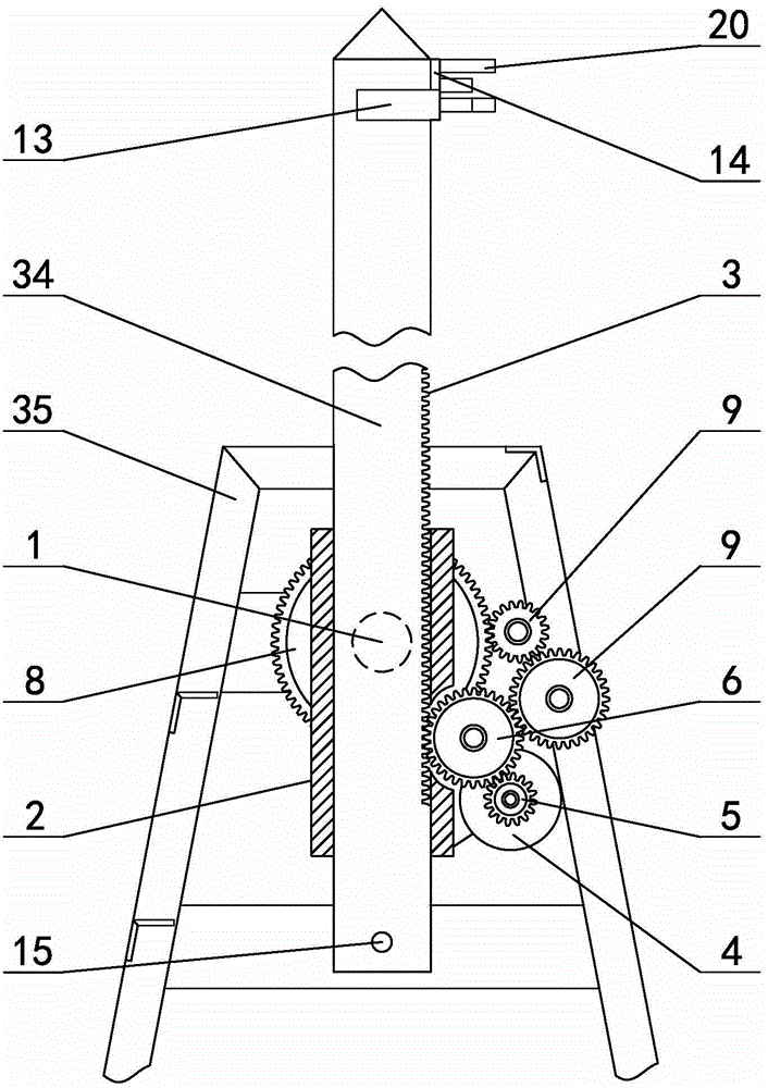
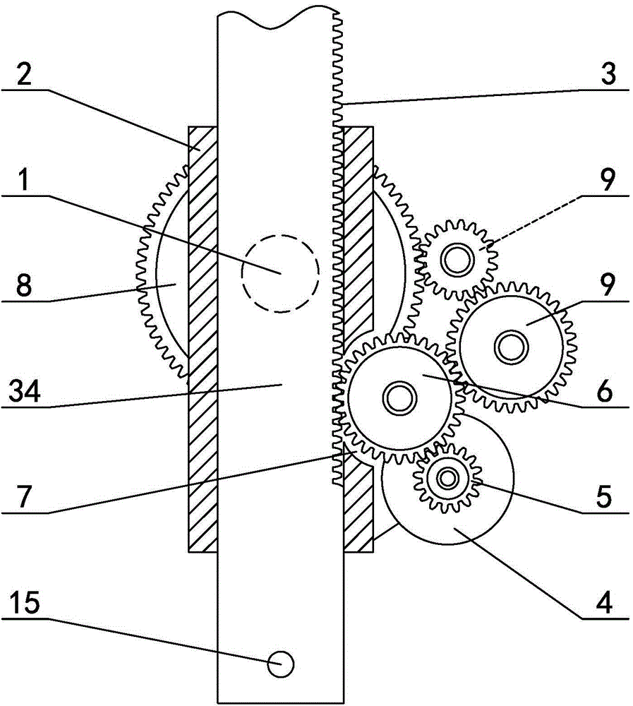
[0034] in such as figure 1 In the shown embodiment 1, a kind of cylindrical mast automatic lifting device, the said cylindrical mast 34 is rotatably arranged on the mast base frame 35 of the ship, the mast base frame is a U-shaped structure with the opening facing upwards, the said mast The base frame is provided with a horizontal rotating shaft 1 perpendicular to the ship's navigation direction, and a sliding sleeve 2 for positioning the mast is fixed in the middle of the horizontal rotating shaft. A rack 3 is arranged, and the outer wall of the sliding sleeve is provided with a mast motor 4 and a support 36 for fixing the gear transmission system (see Figure 4 ), the output shaft of the mast motor is provided with a mast drive gear 5, the mast drive gear meshes with a mast lifting gear 6, and a gap 7 is provided on the side wall corresponding to the sliding sleeve and the rack (see image 3 ), one side of the mast lifting gear meshes with the rack on the mast through the g...

Embodiment 2

[0043] The swing mechanism of embodiment 2 (see Figure 5 ) includes a swing motor (not shown in the figure), the swing motor is a speed-regulating motor, the power shaft 21 of the swing motor is stacked with a forward drive gear 22 and a reverse drive gear 23, the forward drive gear and the reverse drive gear The driving gears are sector gears with the same number of teeth and the same modulus and are arranged in dislocation. The swing mechanism also includes a swing gear 24. The forward drive gear is intermittently meshed with the swing gear, and the reverse drive gear is intermittently meshed with the reversing gear 25. The gear is engaged with the swing gear, and the swing gear is engaged with the swing output gear 27 through a reduction transmission gear 26. When the forward drive gear is engaged with the swing gear, the reverse drive gear is disengaged from the reversing gear, and the reverse drive gear is engaged with the reversing gear. When the gears are engaged, the ...

Embodiment 3

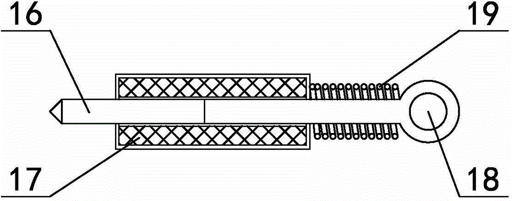
[0046] The mast top of embodiment 3 is provided with emergency anti-collision mechanism (see Figure 6 ), the emergency anti-collision mechanism includes a straight rod 28 and a compression spring 29, the length direction of the straight rod is parallel to the length direction of the ship, the straight rod is slidably worn on the mast, and the front end of the straight rod is provided with a bumper , the compression spring is sleeved on the straight rod, one end of the compression spring is in contact with the impact head, the other end is in contact with the mast, the rear end of the straight rod is provided with a limit plate 31 to prevent the straight rod from coming out, the limit plate The end of the straight rod on the rear side is fixed with a stay cord 32, and the stay cord is connected with the draw ring through a pulley mechanism 33. The obstacle detection device of this embodiment is arranged below the straight rod; a clutch is provided between the mast motor and th...


PUM


Abstract

The invention discloses an automatic lifting device and method of a cylindrical mast. A horizontal rotating shaft is arranged on a mast base frame. A sliding sleeve is fixed to the middle of the horizontal rotating shaft. The mast penetrates in the sliding sleeve. The outer wall of the lower half part of the mast is axially provided with a rack. A mast motor is engaged with the rack through a mast drive gear and a mast lifting gear. The mast base frame is provided with a fixing gear coaxial with the horizontal rotating shaft. The mast lifting gear is engaged with the fixing gear through a reduction gear set. Swinging type obstacle detecting devices are arranged on the two sides of the top of the mast. The automatic lifting device of the cylindrical mast further comprises a control device and an alarm device. The control device is connected with the mast motor, the obstacle detection devices and the alarm device. The automatic lifting device and method effectively solve the problem that a mast lifting device in the prior art is likely to cause collision accidents due to negligence or misjudgment. The automatic lifting device of the cylindrical mast can automatically detect an obstacle and automatically place the mast down, the navigation safety is ensured, and high practical value is achieved.

Description

technical field [0001] The invention relates to the technical field of marine mast lifting, in particular to an automatic columnar mast lifting device and a mast lifting method that can effectively prevent collisions between ship masts and obstacles such as bridges. Background technique [0002] Masts are generally installed on the centerline of the highest ceiling of the ship, and are used to install radar, navigation signal lights and communication antennas, etc., and are very important safety facilities when the ship is sailing. The structure of the mast usually has a single column type, a tower type, etc. When a ship passes under a bridge erected on the water, if the mast on the ship may collide with the bridge, it is necessary to lower (or put down) the mast in advance, and the ship can pass safely after lowering the height. The mast lowering process in the prior art needs to manually determine in advance whether there are obstacles such as bridges ahead and the water ...

Claims


Application Information

Patent Timeline
IPC IPC(8): B63B15/00B63B43/18
Inventor 陈正寿张国辉程枳宁张兆德
Owner ZHEJIANG OCEAN UNIV
Why Eureka
Try Eureka