
Mold for manufacturing goblet on presser

A technology for goblets and moulds, applied in glass blowing machines, glass production, etc., can solve the problems of high production cost, low output, and large labor volume, and achieve increased production capacity, increased color varieties, and reduced labor volume Effect

Inactive Publication Date: 2015-11-25
CHONGQING JIANLI GLASS PROD CO LTD
View PDF3 Cites 2 Cited by
  • Summary
  • Abstract
  • Description
  • Claims
  • Application Information

AI Technical Summary

Problems solved by technology

The production of goblets by blowing the cup body and manually making the cup stem and cup holder has the disadvantages of low output, high production cost, large amount of labor, few changes in the structure of the cup stem and cup holder, and requires skilled workers. Due to the shortcomings of existing processing methods, a new method of producing goblets needs to be explored, and a mold for making goblets with a press is to be explored

Method used


Image

  • Mold for manufacturing goblet on presser

Examples


Embodiment 1

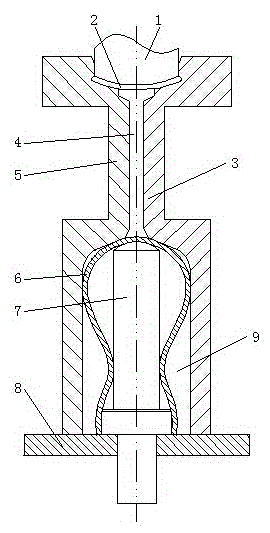
[0017] A mold for making a goblet with a press. The mold has two openings. When the left module 5 and the right module 3 are closed, the inside of the mold forms a cup holder cavity 2, a cup stem cavity 4, and a cup body shape from top to bottom. Cavity 9, the cup body cavity 9 is provided with a push rod 7, the push rod 7 is connected to the chassis 8, and the punch 1 is located on the cup holder cavity 2. The left module 5 and the right module 3 are provided with manual opening and closing latches. The shape of the cup stem cavity 4 can be a geometric shape that the left module 5 and the right module 3 can be demolded after the cup stem is formed. The shape of the cup holder cavity 2 can be a geometric shape in which the left module 5 and the right module 3 can be demolded after the cup holder is formed. Patterns are engraved on the position of the cup holder surface in the cup holder cavity 2 . Pressing machine is a station or a plurality of stations, and a mold is instal...

Embodiment 2

[0019] A mold for making a goblet with a press. The mold has two openings. When the left module 5 and the right module 3 are closed, the inside of the mold forms a cup holder cavity 2, a cup stem cavity 4, and a cup body shape from top to bottom. Cavity 9, the cup body cavity 9 is provided with a push rod 7, the push rod 7 is connected to the chassis 8, and the punch 1 is located on the cup holder cavity 2. The shape of the cup stem cavity 4 can be a geometric shape that the left module 5 and the right module 3 can be demolded after the cup stem is formed. The shape of the cup holder cavity 2 can be a geometric shape in which the left module 5 and the right module 3 can be demolded after the cup holder is formed. Patterns are engraved on the position of the cup holder surface in the cup holder cavity 2 . A connecting rod for automatic opening and closing is connected to the left module 5 and the right module 3 . During automatic mold opening, the left module 5 and the right ...


PUM


Abstract

The invention relates to a mold for manufacturing a goblet on a presser. The mold is characterized by being a two-open mold, wherein the interior of the mold forms a cup stand die cavity, a cup rod die cavity and a cup body die cavity from top to bottom when a left mold block and a right mold block are closed together, an ejector rod is arranged in the cup body die cavity and is connected to a base plate, and a punching head is positioned on the cup stand die cavity. The mold for manufacturing the goblet on the presser is capable of successfully realizing machine blowing and machine pressing combined manufacturing of a glass goblet, the product not only preserves the advantages of blow manufacturing but also is capable of significantly improving the production capacity, so that the product quality is significantly improved, the production cost is greatly reduced, the amount of labor used is greatly reduced, the structures of a cup body, a cup stem and a cup stand are most changeful to significantly increase the colors and patterns of glass goblets, and the mold has significant economical and social benefits and popularization value.

Description

technical field [0001] The invention relates to a mold for a glass press, and more particularly to a mold for making a goblet by a press. Background technique [0002] Glassware molding mold is an indispensable equipment in glassware molding. The quality and output of glassware production are directly related to the mold. There are two methods of glassware molding: pressing and blowing. When pressing special types of glassware, the mold must be opened to take out the pressed glassware. The mold used is a split mold. There are currently two types of split molds, one is two-opening molds, and the other is It is a three-open mold. The glassware processed by the split mold may have the deficiency of two or three outer convex ribs at the joint of the mold. The goblet in the glassware is mainly composed of three parts: the cup body, the cup stem and the cup holder. Most of the current goblets are processed by blowing the cup body, and the cup stem and the cup holder are artific...

Claims


Application Information

Patent Timeline
IPC IPC(8): C03B9/197
CPCY02P40/57
Inventor 唐建
Owner CHONGQING JIANLI GLASS PROD CO LTD
Learn More