Grading-limitation-free slide sleeve and process method
An infinite pole and sliding sleeve technology, applied in the direction of earthwork drilling, production fluid, wellbore/well components, etc., can solve the problem of increasing tool erosion, making it difficult to fully develop the potential of the production layer, and improving the work of the plunger pump of the operating crew Pressure and other issues to achieve the effect of reducing erosion, improving reliability and construction safety, and increasing scale
- Summary
- Abstract
- Description
- Claims
- Application Information
AI Technical Summary
Problems solved by technology
Method used
Image
Examples
Embodiment 1
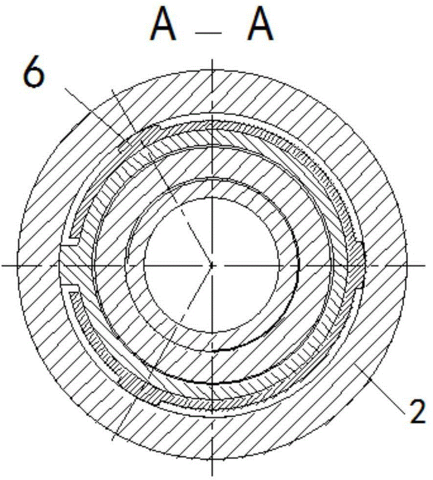
[0037] Embodiment 1: as figure 1 , figure 2 , image 3 , Figure 4 , Figure 5 , Figure 6As shown, it consists of coupling 1, body 2, displacement sliding sleeve 3, first O-ring 4, sliding sleeve shear nail 5, locking ring 6, second O-ring 7, fixing screw 8, lower joint 9, Claw-shaped displacement ball seat 10, sealing ball 11, V-shaped sealing ring 12, spacer ring 13, guiding and fixing ring 14 etc. are formed.
[0038] figure 1 State when the present invention enters the well, figure 2 Put into the sealing displacement mechanism that is made up of 10~14 and open the state when sliding sleeve when the present invention works.
[0039] Infinite grading is achieved like this: figure 1 As shown, the state of the present invention when entering the well is that the coupling 1 is connected to the body 2, and the body 2 has three symmetrical oblong holes. The sleeve 3 seals the oblong hole, the upper end of the displacement sliding sleeve 3 is processed with an annular ...
Embodiment 2
[0043] Embodiment 2: as figure 1 , figure 2 , image 3 , Figure 4 , Figure 5 , Figure 6 As shown, an infinite sliding sleeve consists of a coupling 1, a body 2, a displacement sliding sleeve 3, a first O-ring seal 4, a sliding sleeve shear pin 5, a locking ring 6, and a second O-ring 7, and is fixed Screw 8, lower joint 9, claw-shaped displacement ball seat 10, sealing ball 11, V-shaped sealing ring 12, spacer ring 13, guiding and fixing ring 14, etc. are composed.
[0044] The state when entering the well is that the coupling 1 is connected to the main body 2, the displacement sliding sleeve 3 is arranged in the main body 2, and the lower end of the main body 2 is connected with the lower joint 9.
[0045] The body 2 is provided with three oblong holes, and there are several discontinuous annular grooves in the lower part of the body 2 .
[0046] The body 2 is equipped with a displacement sliding sleeve 3 when entering the well, and the upper and lower ends of the d...
Embodiment 3
[0055] Embodiment 3: as figure 1 , figure 2 , image 3 , Figure 4 , Figure 5 , Figure 6 as shown,
[0056] An infinite pole sliding sleeve can be divided into infinite poles in the same well, and the inner diameter of each level of sliding sleeve is consistent, which can greatly reduce the frictional resistance of liquid flow and is beneficial to increase the processing scale.
[0057] The following is further optimization / and improvement to the technical solution of the present invention:
[0058] The body 2 is symmetrically opened with three long grooves, the equivalent area of which is much larger than the inner diameter area of the tubing, so as to reduce the degree of erosion of the casing and the body by the sand-carrying fluid during fracturing;
[0059] The above-mentioned displacement sliding sleeve is installed in the body and fixed by shear nails; a lock ring is installed between the two;
[0060] When the above-mentioned claw-shaped displacement ball...
PUM
 Abstract
Description
Claims
Application Information
 - R&D
- Intellectual Property
- Life Sciences
- Materials
- Tech Scout
- Unparalleled Data Quality
- Higher Quality Content
- 60% Fewer Hallucinations
Browse by: Latest US Patents, China's latest patents, Technical Efficacy Thesaurus, Application Domain, Technology Topic, Popular Technical Reports.
© 2025 PatSnap. All rights reserved.Legal|Privacy policy|Modern Slavery Act Transparency Statement|Sitemap|About US| Contact US: help@patsnap.com


