

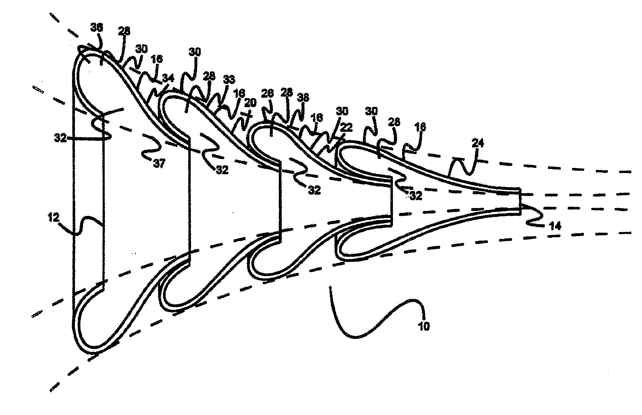
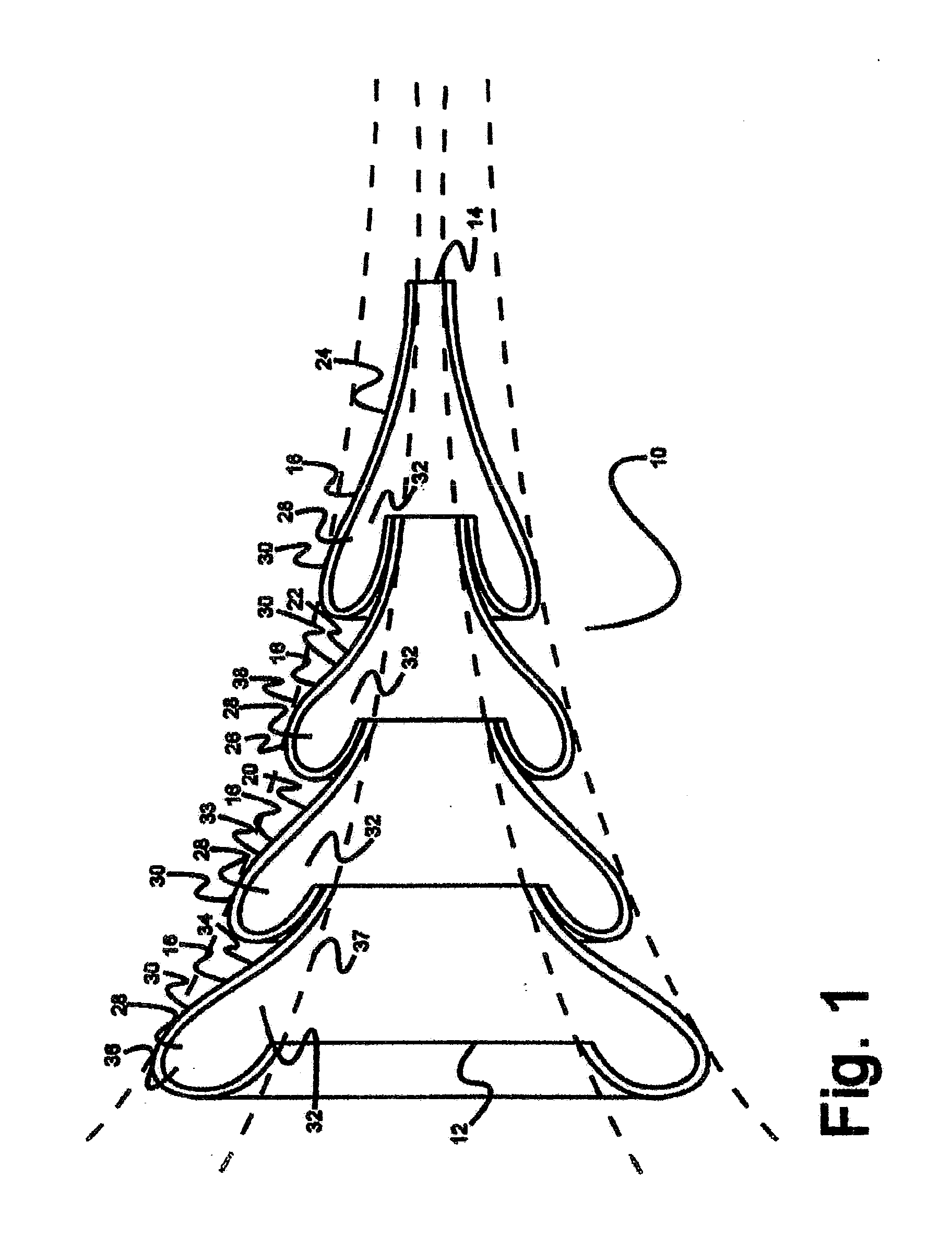
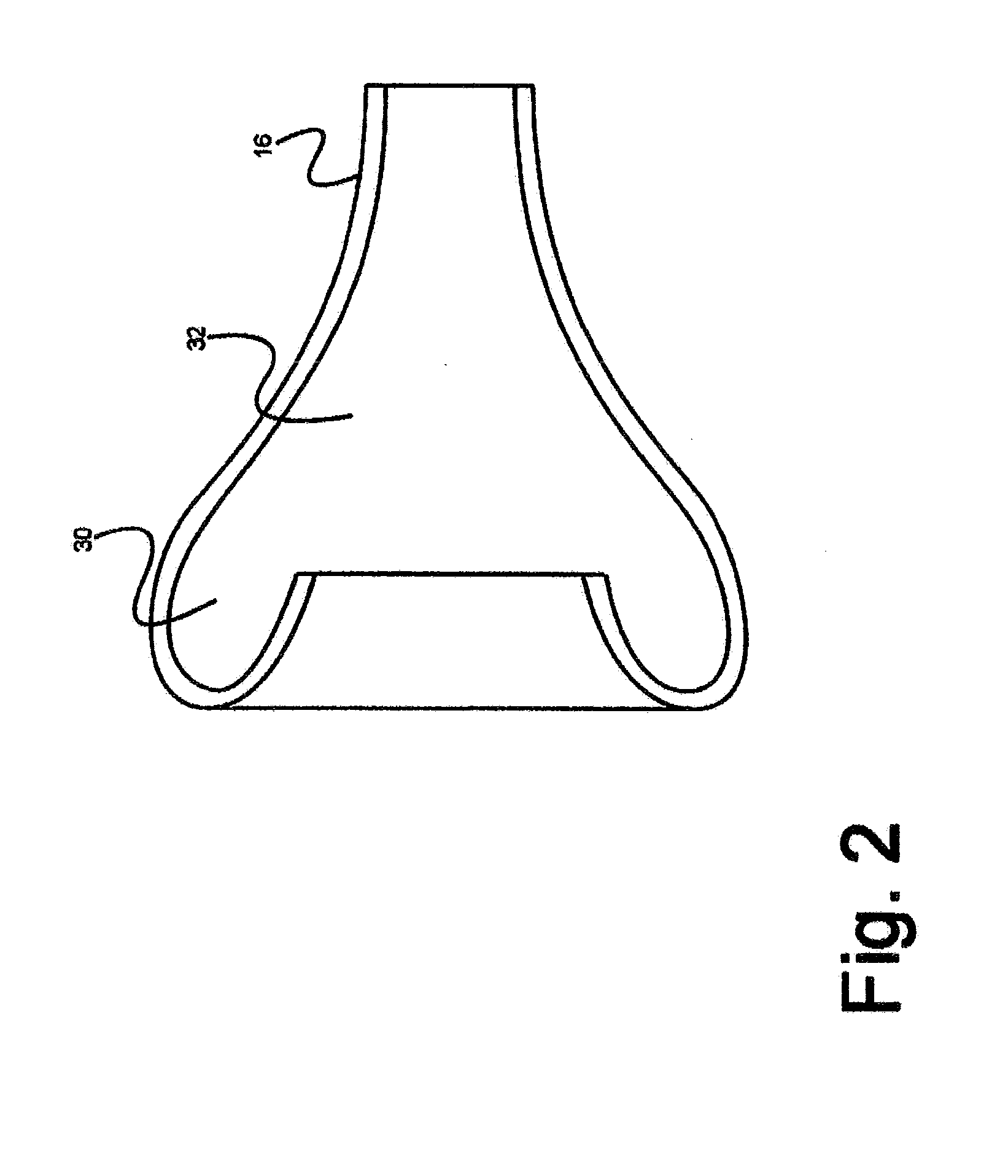
Channeling fluidic waveguide surfaces and tubes
a fluid waveguide and surface technology, applied in the field of tubes, can solve the problems of back pressure impediment, inability to block or interrupt the noisy exhaust stream, weight and scalloping at the trailing edge of the engine nozzle, etc., to reduce frictional resistance, reduce wind resistance, and reduce frictional resistance
- Summary
- Abstract
- Description
- Claims
- Application Information
AI Technical Summary
Benefits of technology
Problems solved by technology
Method used
Image

Examples
Embodiment Construction
[0067]The inventor has conceived, and reduced to practice, channeling gas flow surfaces and tubes that address the challenges and problems in the art outlined above. Various techniques will now be described in detail with reference to a few example embodiments thereof, as illustrated in the accompanying drawings. In the following description, numerous specific details are set forth in order to provide a thorough understanding of one or more aspects and / or features described or referenced herein. However, it will be apparent to one skilled in the art, that one or more aspects and / or features described or referenced herein may be practiced without some or all of these specific details. In other instances, well known process steps and / or structures have not been described in detail in order to not obscure some of the aspects and / or features described or reference herein.
[0068]One or more different inventions may be described in the present application. Further, for one or more of the i...
PUM
 Abstract
Description
Claims
Application Information