
Method for attaching micro bubble array on plate surface

Inactive Publication Date: 2010-07-01
PUSAN NAT UNIV IND UNIV COOPERATION FOUND
View PDF4 Cites 17 Cited by
  • Summary
  • Abstract
  • Description
  • Claims
  • Application Information

AI Technical Summary

Benefits of technology

[0011]In the aforementioned techniques for reducing fluid frictional resistance, the air injection allowing production and control to be easy is actively studied in or out of the country so as to enhance the possibility of practical use in the future.
[0016]An object of the present invention is to provide a method for attaching a micro bubble array to a plate surface, by which it is possible to solve complicated problems such as reduction of propulsive force caused by air injection, corrosion caused by cavitations and external devices required for air injection at a time and to spontaneously generate micro bubbles on a surface as desired at desired locations at the instant of going under water.

Problems solved by technology

However, other studies following Kramer did not give any result supporting the Kramer's consideration, so that the studies on that field have been depressed.
Particularly, in case of ships, optimal depth or width of such grooves is about 0.1 mm, and with a current technology, it is very difficult to solve problems with their production and preventive measures of adhesion of ocean microorganisms to the grooves and the like.
The polymer injection however has drawbacks in that it causes environmental pollution and its resistance reducing effect rapidly disappears due to the deterioration of polymer function.

Method used


Image

  • Method for attaching micro bubble array on plate surface
  • Method for attaching micro bubble array on plate surface
  • Method for attaching micro bubble array on plate surface

Examples


Embodiment Construction

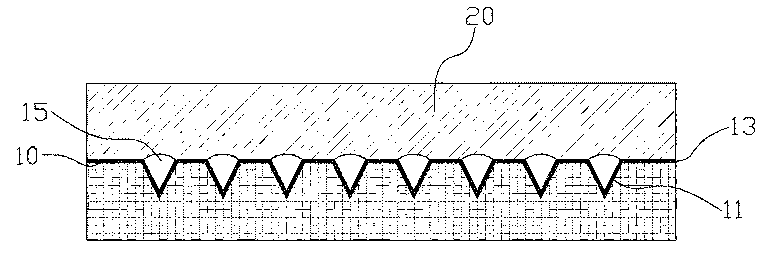
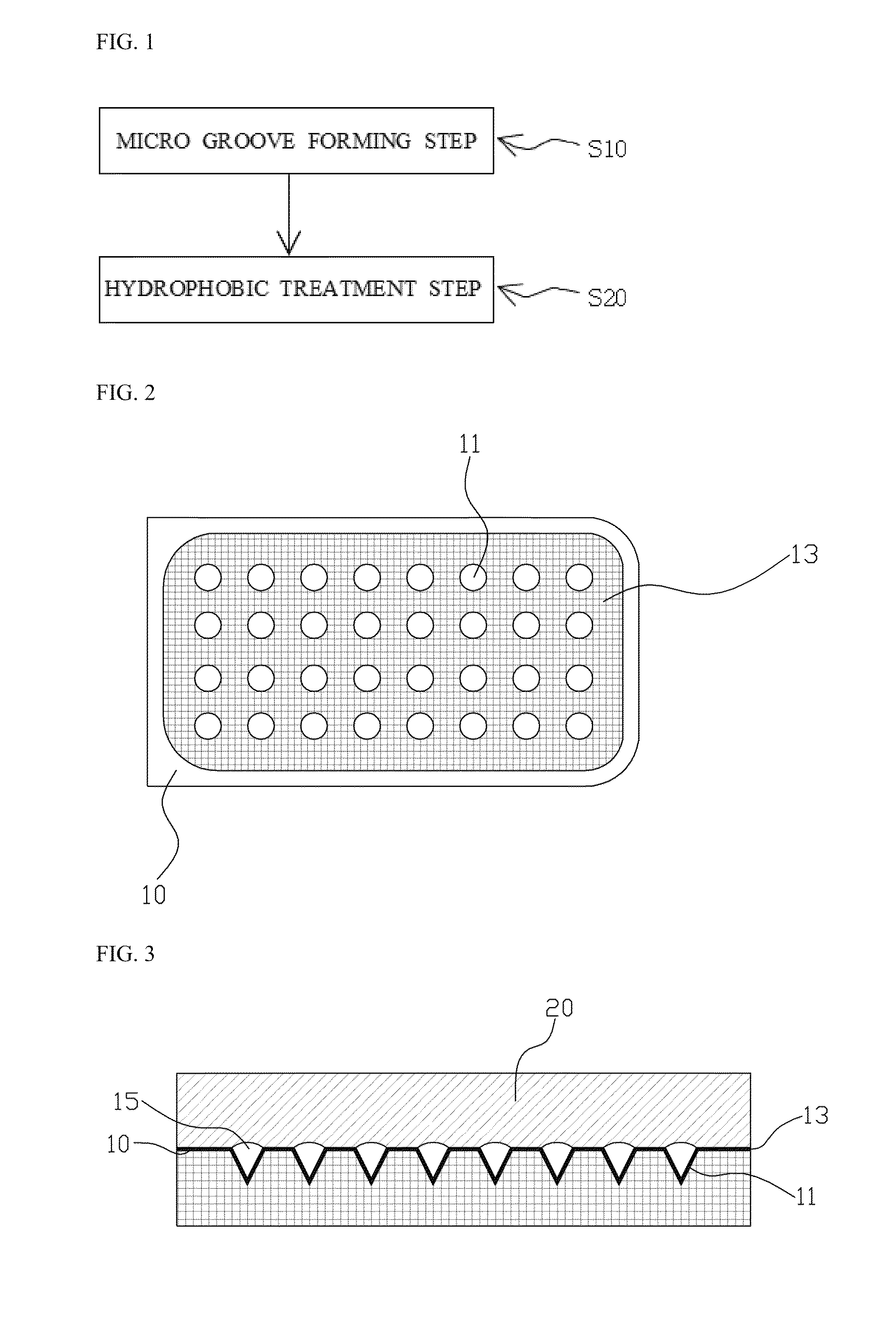
[0027]FIG. 1 is a schematic diagram illustrating a method for attaching a micro bubble array on a plate surface according to one embodiment of the present invention; FIG. 2 is a schematic view showing the plate surface to which the embodiment of FIG. 1 is applied; and FIG. 3 is a sectional view showing the plate surface of FIG. 2, which goes under water.

[0028]A method for attaching a micro bubble array on a plate surface according to one embodiment of the present invention will be described with reference to FIGS. 1 to 3.

[0029]The method for attaching a micro bubble array on a plate surface comprises a micro groove forming step S10 and a hydrophobic treatment step S20.

[0030]In the micro groove forming step S10, grooves 11 with a size of 1 to 1,000 μm are formed in a plate surface 10 to be arranged thereon. The groove 11 has a cross section of various shapes, such as quadrangle, triangle, trapezoid and circle.

[0031]In the hydrophobic treatment step S20, the plate surface 10 having th...


PUM

PropertyMeasurementUnit
Sizeaaaaaaaaaa
Electrical resistanceaaaaaaaaaa
Hydrophobicityaaaaaaaaaa

Abstract

The present invention relates to a method for attaching a micro bubble array on a plate surface, and more particularly, to a method for attaching micro-sized bubbles on a plate surface so as to reduce fluid frictional resistance caused by flow on the plate surface that encounters with liquid.The method for attaching a micro bubble array on a plate surface according to one aspect of the present invention includes a micro groove forming step and a hydrophobic treatment step. In the micro groove forming step, a plurality of grooves with a size of 1 to 1,000 micrometers are formed in a plate surface to be arranged therein. In the hydrophobic treatment step, the plate surface having the grooves formed therein is coated with a material having a hydrophobic property. Since the plate surface has the plurality of grooves arranged therein and also is treated with a hydrophobic material, micro bubbles are formed on the micro grooves when the plate surface goes under water.According to the present invention, the fluid frictional resistance may be reduced using slide occurring between air bubbles and liquid by forming micro bubbles on a plate surface.

Description

CROSS REFERENCE TO RELATED APPLICATIONS[0001]Pursuant to 35 U.S.C. §119(a), this application claims the benefit of earlier filing date and right of priority to Korean Application No. 10-2008-0134480 filed on Dec. 26, 2008, the contents of which are hereby incorporated by reference herein in their entirety.FIELD OF THE INVENTION[0002]The present invention relates to a method for attaching a micro bubble array on a plate surface, and more particularly, to a method for attaching micro-sized bubbles on a plate surface so as to reduce fluid frictional resistance caused by flow on the plate surface that encounters with liquid.DESCRIPTION OF THE RELATED ART[0003]Bubbles each having diameter of micrometer (μm) order size are used in various fields depending on their sizes. For example, bubbles having a size of 10 to 40 μm are used for biological activities, bubbles having a size of 40 to 100 μm are used for fluid physics, and bubbles having a size of 500 to 1000 μm are used for decreasing r...

Claims


Application Information

Patent Timeline
IPC IPC(8): B05D5/08
CPCB32B2038/047B63B1/38B63B2001/387F15D1/10Y02T70/122Y02T70/10B81B1/00B81B7/02B81C1/00
Inventor GO, JEUNG SANGKIM, MOON JEONGKWON, BONG HYUN
Owner PUSAN NAT UNIV IND UNIV COOPERATION FOUND
Learn More