Vehicle and control method thereof

Active Publication Date: 2012-08-23
TOYOTA JIDOSHA KK
View PDF4 Cites 18 Cited by
  • Summary
  • Abstract
  • Description
  • Claims
  • Application Information

AI Technical Summary

Benefits of technology

[0009]In one preferable application of the vehicle of the invention, the vehicle may further have: a transmission that has an input shaft connected via the clutch to an output shaft of the internal combustion engine and connected with a rotating shaft of the motor and transmits power between the input shaft and the driveshaft with a speed change between different speeds, and the controller may control the transmission, in a case that the rotation speed of the motor becomes less than or equal to the predetermined rotation speed if the speed in the transmission is changed to a higher speed level that is a higher speed than a present speed in the transmission in the case of the predetermined stop request time, so that the speed in the transmission is changed to the higher speed level after the clutch is disengaged. This arrangement effectively enables the rotation speed of the motor less than or equal to the predetermined rotation speed in the case of the predetermined stop request time.
[0010]In one preferable application of the vehicle having the transmission of the invention, the controller may control the transmission, in a case that the rotation speed of the motor does not become less than or equal to the predetermined rotation speed even if the speed in the transmission is changed in the case of the predetermined stop request time, so that the speed in the transmission is changed to a highest speed level of the transmission after the clutch is disengaged. This arrangement effectively enhances the possibility of having the rotation speed of the motor less than or equal to the predetermined rotation speed in the case of the predetermined stop request time.

Problems solved by technology

In the case that operation stop of the engine is requested while the vehicle is driven with the clutch engaged in the above vehicle, a relatively long time may be required to lower the rotation speed of the engine passing through a resonance rotation speed band if the clutch is disengaged and fuel injection into the engine is stopped, and may give uncomfortable feeling to the driver and passenger due to noise or vibration of the vehicle caused by the resonance of the vehicle.

Method used


Image

  • Vehicle and control method thereof
  • Vehicle and control method thereof
  • Vehicle and control method thereof

Examples


Embodiment Construction

[0023]One mode of carrying out the invention is discussed below as a preferred embodiment.

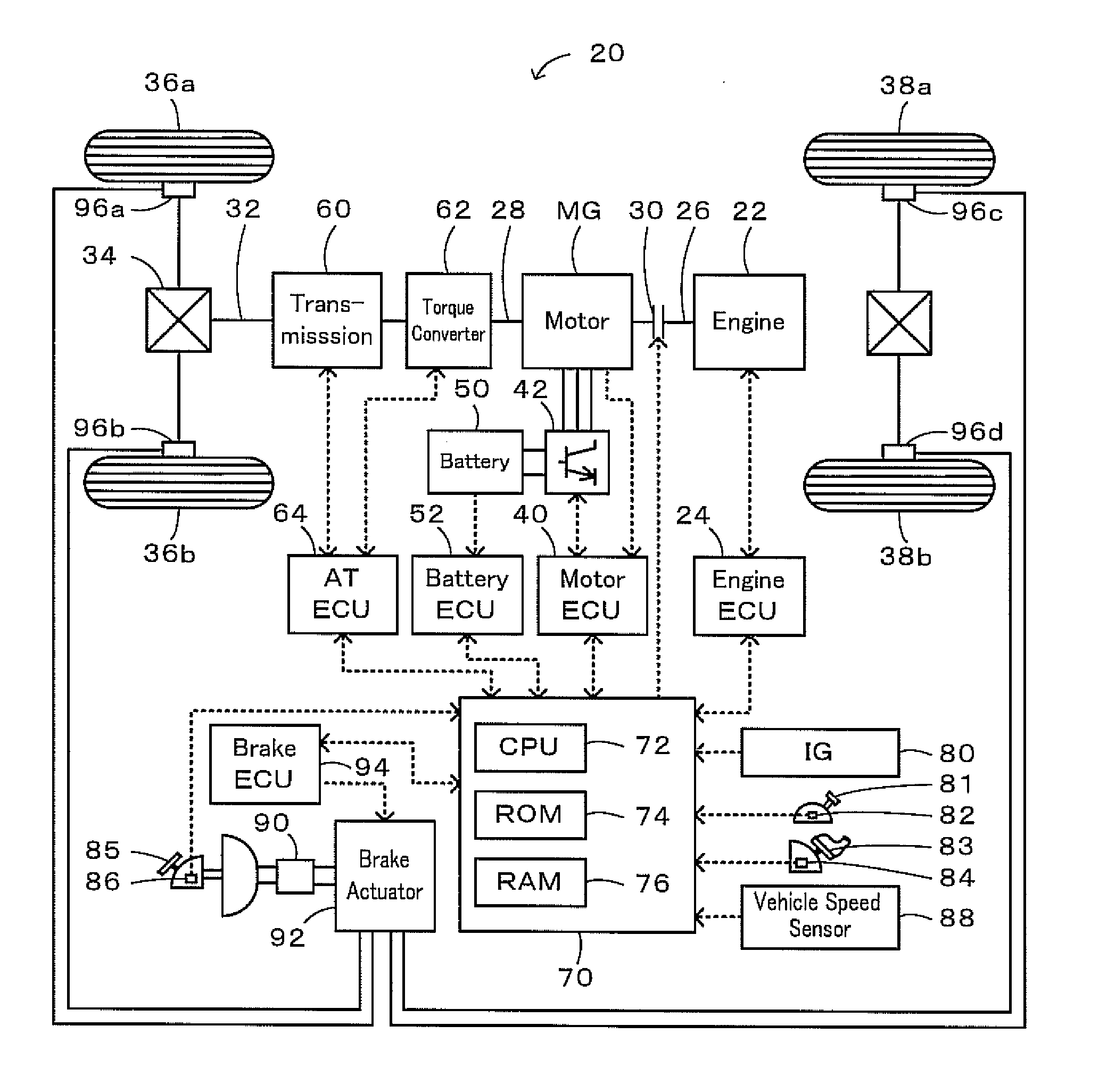
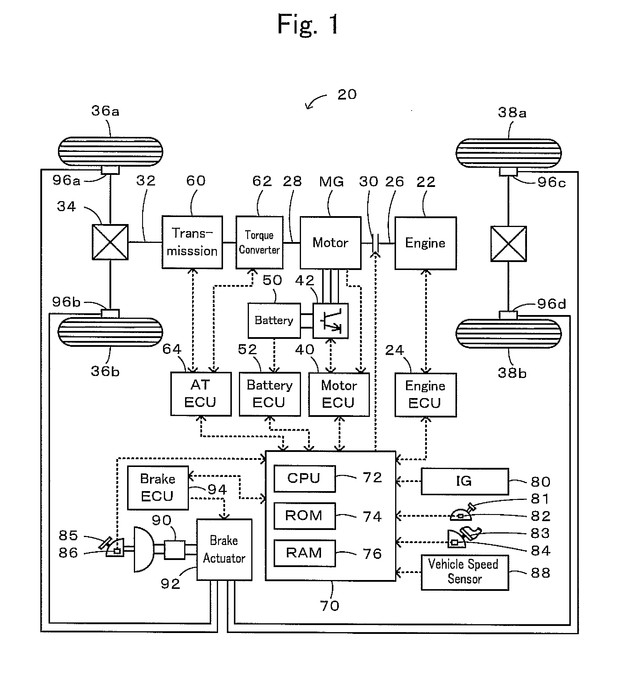
[0024]FIG. 1 schematically illustrates the configuration of a hybrid vehicle 20 in one embodiment of the invention. As illustrated, the hybrid vehicle 20 of the embodiment includes the engine 22, a clutch 30 connected via a non-illustrated damper to a crankshaft 26 or an output shaft of the engine 22 and connected to a power shaft 28, a motor MG connected to the power shaft 28 and designed to have power generation capability, a battery 50 configured to transmit electric power via an inverter 42 to and from the motor MG, a transmission 60 structured to output power to a driveshaft 32 with a speed change in the power output from the engine 22 and the motor MG to the power shaft 28, an brake actuator 92 configured to control brakes of drive wheels 36a and 36b and driven wheels 38a and 38b, and a hybrid electronic control unit 70 configured to control the operations of the whole hybrid vehicle 20.

[...


PUM


Abstract

In the case that operation stop of the engine is requested while the clutch is engaged and the engine is driven at a higher rotation speed than the resonance rotation speed band, the clutch is disengaged and the engine is driven in the self-sustaining operation at the self-sustaining rotation speed higher than the resonance rotation speed band, the rotation speed Ne of the engine is lowered less than or equal to the second rotation speed Nref2 lower than the resonance rotation speed band with stop of fuel injection into the engine and the partially-engaged clutch after the rotation speed Nm of the motor MG becomes less than or equal to the first rotation speed Nref1 predetermined as a rotation speed lower than the resonance rotation speed after the clutch is disengaged. The rotation speed of the engine is therefore enabled to pass more rapidly through the resonance rotation speed band.

Description

TECHNICAL FIELD[0001]The present invention relates to a vehicle and a control method of a vehicle.BACKGROUND ART[0002]One proposed vehicle having an engine, a clutch placed between an output shaft of the engine and a transfer shaft linked to driving wheels, and a motor connected to the transfer shaft, is driven using output power from the engine with the clutch engaged or driven using only output power from the motor with the clutch disengaged (see, for example, Patent Document 1). This vehicle is driven with the clutch disengaged in the case the vehicle speed becomes low or the case the vehicle load becomes small.PRIOR ART DOCUMENTPatent Document[0003]Patent Document 1: Japanese Patent Laid-Open No. H06-38305SUMMARY OF THE INVENTION[0004]In the case that operation stop of the engine is requested while the vehicle is driven with the clutch engaged in the above vehicle, a relatively long time may be required to lower the rotation speed of the engine passing through a resonance rotati...

Claims


Application Information

Patent Timeline
IPC IPC(8): B60W20/00B60W10/18B60W10/02B60W10/06B60W10/08B60L50/16
CPCB60W10/02B60W10/06Y02T10/6286B60W20/00B60W10/08Y02T10/62B60W2510/0208B60W2030/203B60W20/30
Inventor HASHIMOTO, TOSHIYA
Owner TOYOTA JIDOSHA KK
Why Eureka
Try Eureka