Method and apparatus for diagnosing particulate filter

A particle filter and sensor technology, which is applied to the diagnostic device, exhaust device, and noise reduction device of the exhaust gas treatment device, can solve disadvantages and other problems, and achieve the effects of reliable detection, reliable offset tolerance, and increased difficulty

Active Publication Date: 2015-11-25
ROBERT BOSCH GMBH
View PDF8 Cites 18 Cited by
  • Summary
  • Abstract
  • Description
  • Claims
  • Application Information

AI Technical Summary

Problems solved by technology

However, this active intervention is di

Method used


Image

  • Method and apparatus for diagnosing particulate filter
  • Method and apparatus for diagnosing particulate filter
  • Method and apparatus for diagnosing particulate filter

Examples


Embodiment Construction

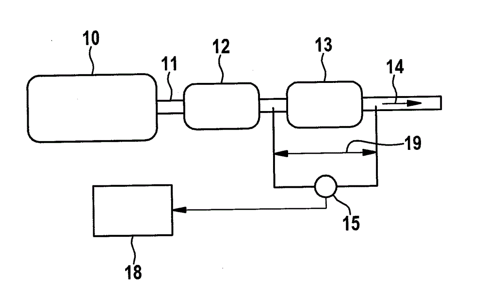
[0031] figure 1 The technical field in which the method according to the invention can be applied is schematically shown. An internal combustion engine 10 is shown as an example, which is embodied as a gasoline motor, wherein the exhaust gas of the internal combustion engine is conducted via an exhaust gas line 11 in which an exhaust gas cleaning device is arranged, which in the example shown is multi-stage Implementation. In the flow direction of the exhaust gas (exhaust gas flow 14 ), in the example shown there is firstly a catalytic converter 12 , which can be designed as a three-way catalytic converter, after which a particle filter 13 is arranged. Furthermore, exhaust gas sensors or other sensors, which of course are not shown in this schematic diagram, are usually arranged in the exhaust gas line 11 , the signals of which are fed to a motor control system (Electronic Control Unit ECU).

[0032] For diagnosing particle filter 13 , according to the prior art, a different...


PUM


Abstract

The invention relates to a method for diagnosing a particulate filter as part of an exhaust gas cleaning system in the exhaust system of an internal combustion engine. In order to monitor the particulate filter, a differential pressure between the inlet and outlet of the particulate filter is measured and is evaluated in a diagnostic unit. The invention further relates to a device, in particular a diagnostic unit. According to the invention, in order to identify the detachment of the particle filter or a damaged particle filter, the time gradient of the measured differential pressure set at the particulate filter is in correlation with an expected temporal gradient of a differential pressure of a reference particulate filter with normal functions and the correlation is evaluated. Compared with the prior art, the method has the advantage that even at very low absolute pressure differences, and under the condition that the gasoline direct injection is used as the internal combustion engine, the detachment diagnosis is realized without the need for the extra active intervention, e.g. the mass flow is improved or a throttle turn plate is opened during the inertia driving.

Description

technical field [0001] The invention relates to a method for diagnosing a particle filter as part of an exhaust gas cleaning system in the exhaust gas line of an internal combustion engine, wherein, in order to monitor the particle filter, a measurement is made at the particle filter The pressure difference between the inlet and outlet of the tester and this pressure difference is evaluated in a diagnostic unit. [0002] The invention also relates to a device, in particular a diagnostic unit, for carrying out the method according to the invention. Background technique [0003] Emission regulations, especially in the United States and Europe, set emission limit values ​​for particle mass and particle number or particle concentration. In addition to the emission limit values, diagnostic limit values ​​are likewise specified, if these diagnostic limit values ​​are exceeded, a fault must be indicated. To this end, a diagnostic function is carried out in the vehicle, which moni...

Claims


Application Information

Patent Timeline
IPC IPC(8): F01N11/00F01N3/021
CPCF01N3/021F01N11/00F01N2550/04F01N2550/24F01N2900/0418F01N2900/08F01N2900/1406Y02T10/12Y02T10/40
Inventor T.蔡因连运捷
Owner ROBERT BOSCH GMBH
Why Eureka
Try Eureka