Fluid pressure control device

一种控制装置、液压的技术,应用在阀装置、流体压力致动装置、阀的操作/释放装置等方向,能够解决制造成本升高、不利等问题,达到减少组装工序、节省成本、制造容易的效果

Active Publication Date: 2015-11-25
HITACHI ASTEMO LTD
View PDF6 Cites 3 Cited by
  • Summary
  • Abstract
  • Description
  • Claims
  • Application Information

AI Technical Summary

Problems solved by technology

[0004] However, in the above-mentioned conventional hydraulic control device, since the fixed iron core and the solenoid case (yoke) are integrally formed by forging, etc., there is a disadvantage in that the manufacturing cost increases.
In addition, since a part of the valve part of the electromagnetic three-way valve is combined with a part of the solenoid part to realize integration, therefore, when the structural part of the solenoid part is also used in other solenoid valves with different structures of the valve part (such as Electromagnetic 2-way valve) is an unfavorable structure in terms of cost savings

Method used


Image

  • Fluid pressure control device
  • Fluid pressure control device
  • Fluid pressure control device

Examples


Embodiment Construction

[0051] Hereinafter, an embodiment of the present invention will be described based on one embodiment of the present invention shown in the drawings.

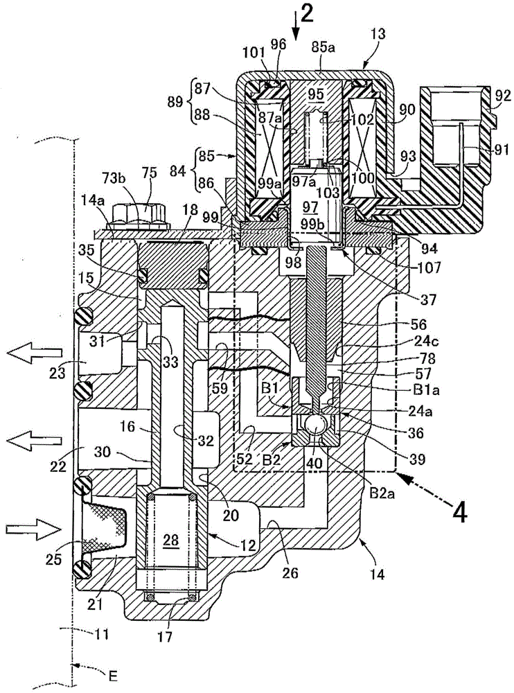
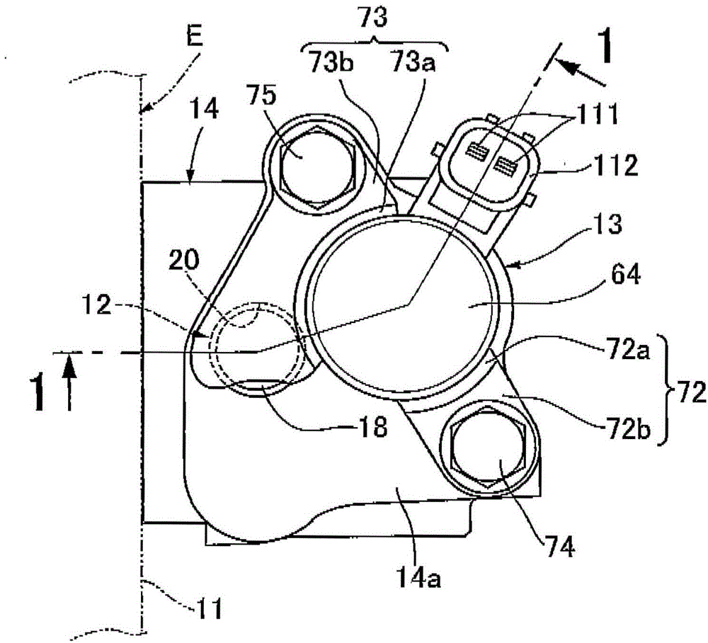
[0052] First, in figure 1 and figure 2 Among them, the hydraulic pressure control device is, for example, a device that switches the hydraulic pressure to high and low and acts on the valve train in order to change the operating characteristics of the valve train in the engine E mounted on the vehicle. It includes: a slide valve 12, which It has a valve body 14 fastened to the engine main body 11 of the engine E; and an electromagnetic three-way valve 13 that connects a hydraulic pressure source such as a hydraulic pump built in the engine main body 11 between the pilot chamber 15 provided in the spool valve 12 . Installed on the valve body 14 in a manner between. As will be described later, the electromagnetic three-way valve 13 is detachably attached to the valve body 14 by fastening the pair of mounting brackets 72 and 73 fi...


PUM


Abstract

A solenoid section of a solenoid three-way valve includes a yoke attached to a valve housing and formed from a bottomed cylindrical main yoke and an auxiliary yoke closing an open end of the main yoke, a coil assembly inside the yoke, a fixed core slidably fitted into a hollow portion of a bobbin and abutted against a ceiling wall of the main yoke, a movable core facing the fixed core and passing through the auxiliary yoke, and a coil spring compressed between the cores. The fixed core is abutted against the wall by a predetermined spring load and by electromagnetic attraction force between the core and wall based on coil energization. A valve rod is slidably supported in a housing hole, having one end separably abutted against an outer end of the movable core and an opposite end abutted against a valve body.

Description

technical field [0001] The present invention relates to the improvement of the hydraulic control device. The hydraulic control device includes: a slide valve, which selectively switches the connection or cut-off of the output port, the input port, and the release port according to the action / release hydraulic pressure on the pilot chamber; and the electromagnetic three-way The valve alternately switches between a state where the hydraulic pressure is applied to the pilot chamber from the input port, and a state where the hydraulic pressure in the pilot chamber is released. Background technique [0002] It is known from the following patent documents that, in the hydraulic control device, the spool valve and the electromagnetic three-way valve are arranged on the valve body so that their axes are parallel, and the direction along the axis of these valves can be adjusted. The miniaturization of the valve body, that is, the hydraulic control device, is achieved, and the slide v...

Claims


Application Information

Patent Timeline
Patent Type & Authority Applications(China)
IPC IPC(8): F16K11/07F16K31/42F16K31/06
CPCY10T137/86879F16K11/0716F16K31/0631F16K31/0675F16K31/423F16K31/426Y10T137/86582Y10T137/86614F16K11/07F16K11/06F16K31/061F15B13/043
Inventor 及川直树山中健太郎
Owner HITACHI ASTEMO LTD
Why Eureka
Try Eureka