Illumination device having broad lighting distribution

一种照明装置、出光部的技术,应用在照明装置、照明装置的零部件、照明和加热设备等方向,能够解决照明装置1出光分布狭窄、限制等问题,达到照度更佳、增加反射角度的效果

Active Publication Date: 2015-11-25
EPISTAR CORP
View PDF10 Cites 1 Cited by
  • Summary
  • Abstract
  • Description
  • Claims
  • Application Information

AI Technical Summary

Problems solved by technology

like figure 2 As shown, the light distribution of the lighting device 1 is narrow and limited

Method used


Image

  • Illumination device having broad lighting distribution
  • Illumination device having broad lighting distribution
  • Illumination device having broad lighting distribution

Examples


Embodiment Construction

[0031] The present invention will be described in detail below in conjunction with specific embodiments shown in the accompanying drawings. However, these embodiments do not limit the present invention, and any structural, method, or functional changes made by those skilled in the art according to these embodiments are included in the protection scope of the present invention.

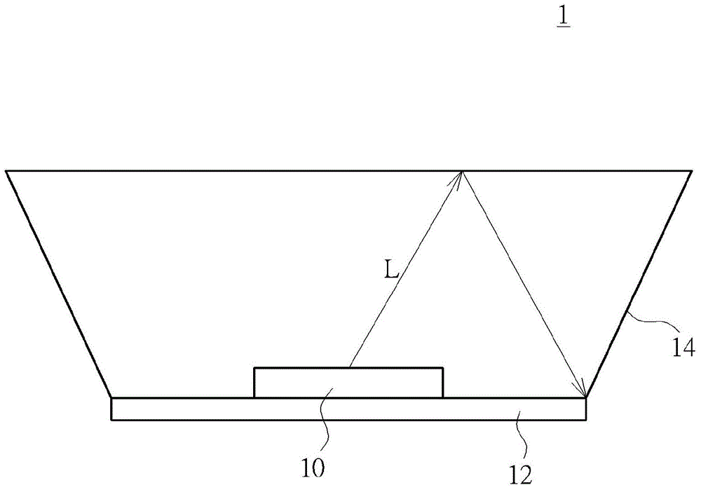
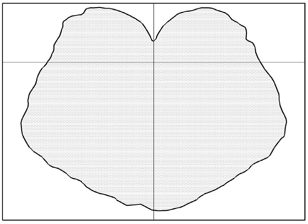
[0032] Please refer to image 3 and Figure 4 , image 3 It is a sectional view of the lighting device 2 according to the first embodiment of the present invention, Figure 4 It is a light distribution curve diagram of the lighting device 2 according to the first embodiment of the present invention. The lighting device 2 includes at least one light-emitting semiconductor element 50 , a supporting base 52 and a lampshade 54 . The light emitting semiconductor device 50 is disposed on the carrier 52 and emits light L, and the lampshade 54 is disposed on the carrier 52 and covers the light emitting sem...


PUM


Abstract

An illumination device includes at least one semiconductor light emitting element, a supporting base, and a lamp housing. The semiconductor light emitting element is disposed on the supporting base. The lamp housing is disposed on the supporting base to cover the semiconductor light emitting element, and includes a first illuminating part and a lateral illuminating part surrounding the first illuminating part. A micro-structure is formed on a side of the first illuminating part and facing the semiconductor light emitting element for reflecting the light emitted from the semiconductor light emitting element.

Description

technical field [0001] The invention relates to an illuminating device, in particular to an illuminating device comprising a light-emitting semiconductor element and a microstructure and having a wide-angle light distribution. Background technique [0002] With the development of science and technology, light-emitting diodes (LEDs) have been widely used in people's lives. LED has the advantages of fast response, small size, low pollution, low power consumption, high reliability and long product life, so it can be used in lighting or display screens. General traditional lighting bulbs, such as incandescent bulbs, can be replaced by LED lighting devices. However, the light beam emitted by the LED is a directional light source, which is different from the traditional diffuse light source, and is subject to many limitations in application. Therefore, the conventional LED lighting device still cannot completely replace the traditional lighting bulb. [0003] Please refer to f...

Claims


Application Information

Patent Timeline
Patent Type & Authority Applications(China)
IPC IPC(8): F21S2/00F21V3/02F21V3/04F21V7/22F21Y101/02
CPCH01L33/58H01L33/54F21V3/02F21V3/04F21V7/22F21K9/65
Inventor 叶志庭简奉任
Owner EPISTAR CORP
Why Eureka
Try Eureka