Laser collimator and laser system

A laser collimation and optical fiber technology, applied in optics, instruments, optical components, etc., can solve problems such as adverse effects of stability and safety, and achieve the goal of avoiding stability and safety, avoiding adverse effects, and increasing the reflection angle. Effect

Pending Publication Date: 2019-06-14
WUHAN RAYCUS FIBER LASER TECHNOLOGY CO LTD
View PDF0 Cites 0 Cited by
  • Summary
  • Abstract
  • Description
  • Claims
  • Application Information

AI Technical Summary

Problems solved by technology

[0004] The invention provides a laser collimator and a laser system to solve the adverse effect

Method used


Image

  • Laser collimator and laser system
  • Laser collimator and laser system
  • Laser collimator and laser system

Examples


Embodiment Construction

[0023] In order to make the purposes, technical solutions and advantages of the embodiments of the present invention clearer, the technical solutions in the embodiments of the present invention will be clearly and completely described below with reference to the accompanying drawings in the embodiments of the present invention. Obviously, the described embodiments These are some embodiments of the present invention, but not all embodiments. Based on the embodiments of the present invention, all other embodiments obtained by those of ordinary skill in the art without creative efforts shall fall within the protection scope of the present invention.

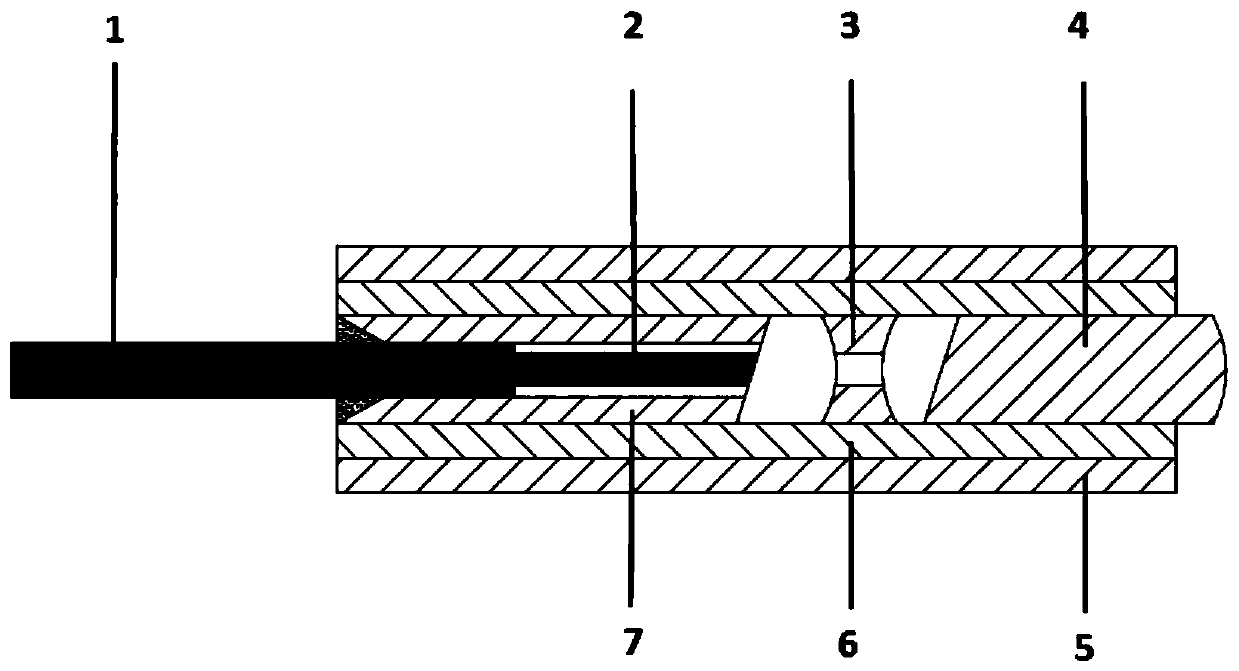
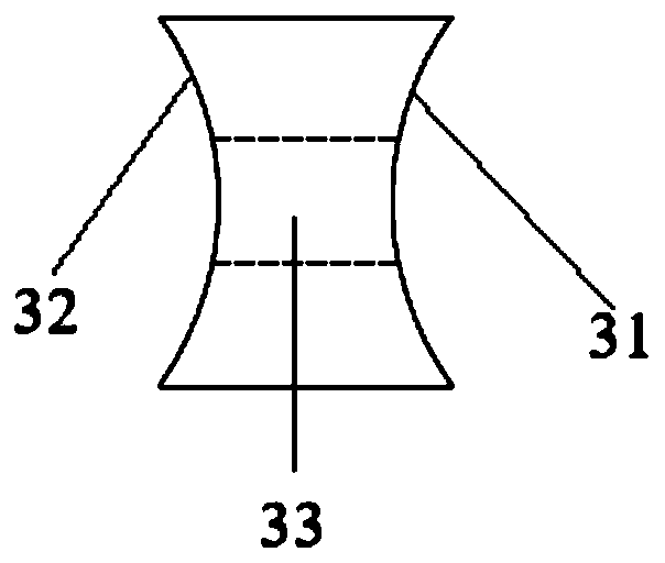
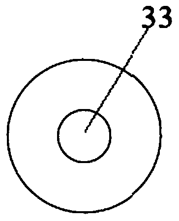
[0024] see figure 1 and figure 2 As shown, an embodiment of the present invention provides a laser collimator, including an optical fiber, a first lens 3 and a second lens 4; the optical fiber, the first lens 3 and the second lens 4 are sequentially arranged along the axis of the optical fiber; the first lens The lens 3 has a thr...


PUM


Abstract

The invention relates to the technical field of laser output equipment, and provides a laser collimator and a laser system. The laser collimator comprises an optical fiber, a first lens and a second lens; the optical fiber, the first lens and the second lens are sequentially arranged and distributed in the axis direction of the optical fiber; a through hole is formed in the first lens, and the through hole penetrates through the first lens in the axis direction of the optical fiber; and the first lens includes a first concave surface, and the first concave surface faces the second lens or theoptical fiber. The laser collimator and the laser system can effectively reduce the adverse effect of the return light on the laser system and improve the stability and security of the system operation.

Description

technical field [0001] The present invention relates to the technical field of laser output equipment, in particular to a laser collimator and a laser system. Background technique [0002] Fiber lasers are lasers that use rare-earth-doped glass fiber as the gain medium. Due to its low cost, miniaturization, and obvious advantages of intensification, and its high electro-optical efficiency and power, it has a wide range of applications. And, with the development of high-power fiber laser applications, fiber lasers are widely used in parts marking, cutting, drilling, welding, cleaning and medical surgery. The most common ones in the market are used for laser marking, laser cleaning, and different processing materials. In the process of laser application, the intensity of the returned light is also different. The higher the power of the laser, the stronger the return light will be. Excessive return light can easily cause damage to the system and even damage the laser. There...

Claims


Application Information

Patent Timeline
IPC IPC(8): G02B6/26G02B27/30
Inventor 谢绍平王佳旭张永平刘开威
Owner WUHAN RAYCUS FIBER LASER TECHNOLOGY CO LTD
Why Eureka
Try Eureka