LED filament and filament type LED bulb

A technology of LED filaments and LED chips, applied in lighting and heating equipment, electrical components, circuits, etc., can solve problems such as component failure, conductive pins 15 of LED filaments falling off, breaking, etc., to increase bonding strength and bonding area Effect

Active Publication Date: 2015-11-25
KAISTAR LIGHTING (XIAMEN) CO LTD +1
View PDF5 Cites 50 Cited by
  • Summary
  • Abstract
  • Description
  • Claims
  • Application Information

AI Technical Summary

Problems solved by technology

In the production process of the existing filament-type LED light bulbs, when the LED filament is assembled to the stem, it is mostly manually assembled, because the position of the electrode E0 on the stem may be inconsistent (for example figure 1 The position of the solid line circle and the dotted line circle in ), and in order to make the conductive pin 15 of the LED filament join with the electrode E0 on the stem, it is necessary to use an external force to fit the two together and combine them by electric welding, so when electric welding aligns There is a pull / push external force on the conductive pin 15 of the LED filament, which may easily cause the conductive pin 15 of the LED filament to fall off or break, resulting in component failure

Method used


Image

  • LED filament and filament type LED bulb
  • LED filament and filament type LED bulb
  • LED filament and filament type LED bulb

Examples


no. 1 example

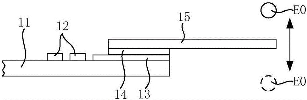
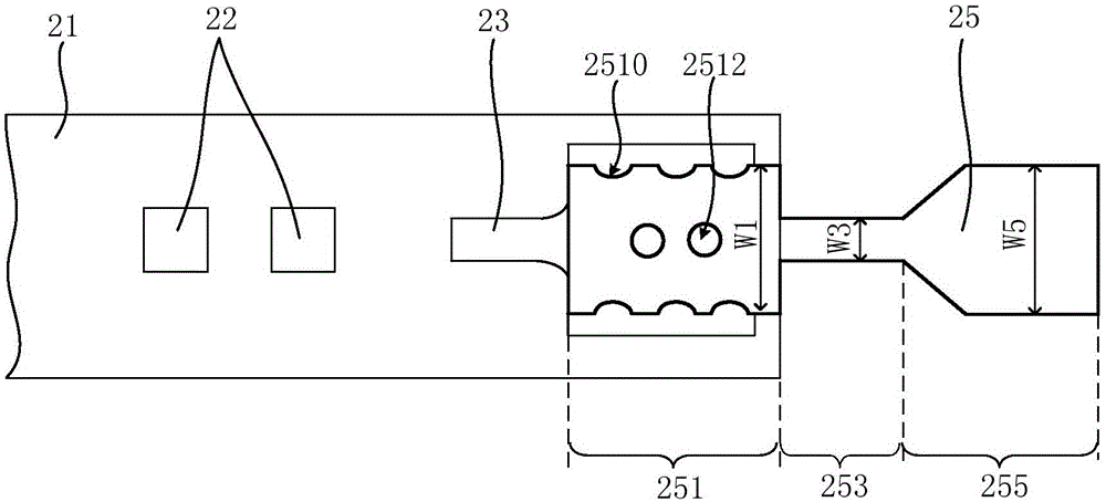
[0033] See Figure 2A , The LED filament provided by the first embodiment of the present invention includes: a carrier 21 , a plurality of LED chips 22 arranged on the carrier 21 , and conductive pins 25 fixedly connected to the carrier 21 . Wherein, the carrier 21 is used to carry the LED chip 22, which is, for example, a light-transmitting material such as transparent ceramics, sapphire or glass substrate; a plurality of LED chips 22 are connected in series, parallel or series-parallel, and are usually fixed on the carrier 21. Each LED chip 22 can form an electrical connection through a metal wire and be connected to a conductive electrode 23 pasted or printed on the carrier 21, where the conductive electrode 23 is, for example, a silver conductive pad (Agpad); the conductive pin 25 It is electrically connected with a plurality of LED chips 22 to provide external power to a plurality of LED chips 22, which includes a pin head 251, a pin tail 255, and a pin neck 253 connectin...

no. 2 example

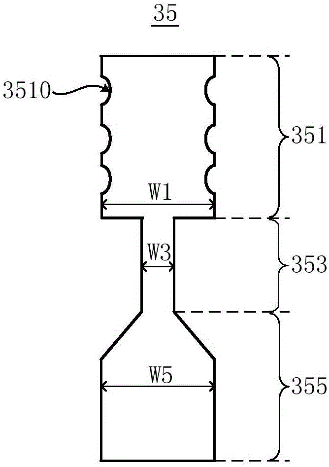
[0036] See Figure 2B A conductive pin 35 for LED filament provided by the second embodiment of the present invention includes: a pin head 351, a pin tail 355, and a pin neck 353 connecting the pin head 351 and the pin tail 355, The pin head 351 , the pin neck 353 and the pin tail 355 are typically of an integral structure.

[0037]Both sides of the pin head 351 are provided with arc-shaped recesses 3510 , so that the bonding area between the pin head 351 and the carrier 21 can be increased, thereby increasing the bonding strength between the pin head 351 and the carrier 21 . The two sides of the pin neck 353 are retracted relative to the pin head 351, that is, the pin neck 353 is retracted in the width direction relative to the pin head 351, so as to reduce the physical width of the pin neck 353 And become the weak point of the conductive pin 35 . The two sides of the pin tail portion 355 are not retracted relative to the pin head 351 , and neither side is provided with a r...

no. 3 example

[0039] See Figure 2C A conductive pin 45 for LED filament provided by the third embodiment of the present invention includes: a pin head 451, a pin tail 455, and a pin neck 453 connecting the pin head 451 and the pin tail 455, The pin head 451 , the pin neck 453 and the pin tail 455 are typically integral structures.

[0040] The two sides of the pin head 451 are provided with arc-shaped recesses 4510 and the middle part is provided with a circular through hole 4512, so that the bonding area between the pin head 451 and the carrier 21 can be increased, thereby increasing the distance between the pin head 451 and the carrier 21. Then intensity. The two sides of the pin neck 453 and the two sides of the pin tail 455 are all retracted relative to the pin head 451, that is, the pin neck 453 and the pin tail 455 are at a width relative to the pin head 451. The overall shrinkage in the direction reduces the physical width of the pin neck 453 and becomes the weak point of the cond...


PUM


Abstract

The invention relates to an LED filament and a filament type LED bulb using the LED filament. The LED filament comprises a carrier, LED chips arranged on the carrier, and an electric conduction pin fixedly connected with the carrier. The electric conduction pin is electrically connected with the LED chips. The electric conduction pin comprises a pin head part, a pin tail part and a pin neck part used connected with the pin head part and the pin tail part. The entity width of the pin neck part is smaller than the maximum entity width of the pin head part. The pin neck part with the reduced entity width is obtained through the mode of internally reducing the width of the pin head part relative to the pin neck part or opening a through hole in the pin neck part or other modes, the pin neck part becomes a weak point of the electric conduction pin; and in this way, when stress is generated, the pin neck part acts firstly, and the joint of the pin head part and the carrier or the carrier itself can be protected.

Description

technical field [0001] The invention relates to the technical field of LED lighting, in particular to an LED filament and a filament-type LED bulb. Background technique [0002] A light emitting diode (Light Emitting Diode, LED) is a solid-state semiconductor device capable of converting electrical energy into visible light, which can directly convert electrical energy into light. Because LED light sources have the characteristics of energy saving, long life, and environmental protection, LEDs are an ideal light source to replace traditional light sources and have a wide range of uses. [0003] Existing filament-type LED light bulbs generally include LED filaments, stems, light-transmitting lampshades such as spherical lampshades, and lamp caps such as threaded lamp caps; wherein, the light-transmitting lampshades and stems are fixedly connected to the lamp caps, and the stems are accommodated in the light-transmitting lampshades And an electrode is arranged on it so as to ...

Claims


Application Information

Patent Timeline
Patent Type & Authority Applications(China)
IPC IPC(8): F21S2/00F21V23/06F21Y101/02
CPCH01L33/62F21K9/232F21V19/003F21V23/06
Inventor 钟宇竣杨健理刘弘智
Owner KAISTAR LIGHTING (XIAMEN) CO LTD
Why Eureka
Try Eureka