Baffle rod type heat exchanger with built-in expansion joint

A technology of expansion joints and baffle rods, which is applied in the field of shell-and-tube heat exchangers, can solve problems such as difficult design, large resistance, and reduced flow resistance of tubes, achieve good sealing and disassembly effects, reduce material usage, and improve The effect of heat transfer efficiency

Inactive Publication Date: 2015-11-25
CHANGZHENG ENG
View PDF12 Cites 7 Cited by
  • Summary
  • Abstract
  • Description
  • Claims
  • Application Information

AI Technical Summary

Problems solved by technology

The traditional shell-and-tube heat exchangers have their own disadvantages: the structure of the floating head heat exchanger is relatively complex; the U-shaped tube heat exchanger has a long process flow, large resistance, and large diameter; the fixed tube-sheet heat exchanger will be affected by temperature difference and cannot replace the tube bundle Cleaning; stuffed box heat exchangers are generally used in low pressure conditions, and the packing seal is easy to leak
[0004] 1. The temperature difference between the two sides of the tube shell side of the heat exchanger is large, and the thermal expansion of the tube bundle and the shell side cylinder is different after heating, resulting in a large displacement difference, causing a large axial temperature difference stress; the traditional heat transfer solution for the tube shell temperature difference stress Generally, the expansion joint is set on the shell. When the pressure is high and the diameter is large, the wall thickness of the expansion joint is large, the compensation amount is small, and the design is difficult;
[0005] 2. The U-shaped tube heat exchanger has at least two tube passes, and a single channel cannot be used to reduce the flow resistance of the tube pass, and increasing the diameter of the U-shaped tube heat exchanger will increase the design difficulty and manufacturing cost;
[0006] 3. The pressure on the tube shell side of the heat exchanger is high but the pressure difference is not large. The structure of the tube sheet and expansion joint is too high in quality according to the full pressure design, and the cost is high;
[0007] 4. The equipment will accumulate dross after running for a period of time, and often needs to be disassembled, cleaned and repaired. If the general flange connection type is used, the structure will be too complicated;
[0008] 5. Traditional heat exchangers guide flow and exchange heat by setting baffles on the shell side, and the baffles will also increase the flow resistance of the shell side

Method used


Image

  • Baffle rod type heat exchanger with built-in expansion joint
  • Baffle rod type heat exchanger with built-in expansion joint
  • Baffle rod type heat exchanger with built-in expansion joint

Examples


specific Embodiment approach

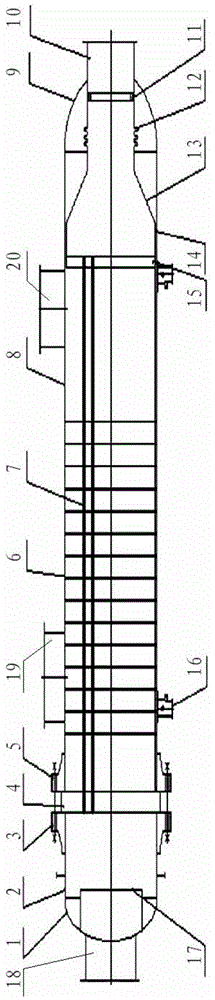
[0038] The invention discloses a baffle rod heat exchanger with built-in expansion joints. figure 1 A specific embodiment of the present invention is shown, such as figure 1 As shown, a baffle rod heat exchanger with a built-in expansion joint shown in this embodiment includes a tube box head 1, a tube box cylinder 2, a tube box flange 3, a left tube plate 4, a tube Body flange 5, support plate 6, heat exchange tube 7, shell side cylinder 8, spherical head, reinforcing tube 10, flange ring 11, expansion joint 12, conical head 13, short joint 14, right tube plate 15. Saddle 16, gas distributor 17;

[0039] Tube box head 1, tube box body 2, tube box flange 3, and gas distributor 17 form a tube box; cylinder body flange 5 consists of shell-side shell body 8, ball head, reinforcing tube 10, and saddle 16 The shell assembly, the flange ring 11 and the expansion joint 12 form the expansion joint assembly, and the remaining components form the tube bundle assembly;

[0040] Such a...


PUM


Abstract

The invention discloses a baffle rod type heat exchanger with a built-in expansion joint. The baffle rod type heat exchanger with the built-in expansion joint comprises a tube box assembly, a shell assembly, a tube bundle assembly and an expansion joint assembly, wherein the tube box assembly comprises a tube box cylinder, a tube box end socket, a tube box flange, a gas inlet and a gas distributor; the tube bundle assembly comprises a tube bundle, a left tube plate and a right tube plate are arranged at the two ends of the tube bundle, and the tube bundle assembly further comprises a short joint and a conical end socket; the expansion joint assembly comprises the expansion joint and a flange ring; the shell assembly comprises a shell pass cylinder, a shell pass end socket and a reinforcing tube; the tube bundle assembly is positioned in the shell pass cylinder, and the reinforcing tube extends to the outer part of the shell pass end socket from the inner part of the shell pass end socket; a cylinder flange is mounted at the end, close to the tube box, of the shell pass cylinder, and the left tube plate is clamped by the cylinder flange and the tube box flange of the tube box assembly; the right tube plate adopts a floating structure and is connected with the big end of the conical end socket through the short joint; and the small end of the conical end socket is connected with the expansion joint, the flange ring is positioned at the end part of the expansion joint, and the flange ring is hermetically connected with the end part of the reinforcing tube of the shell assembly.

Description

technical field [0001] The invention relates to a heat exchanger, in particular to a shell-and-tube heat exchanger in a chemical enterprise. Background technique [0002] Heat exchangers are common equipment in chemical companies. The traditional shell-and-tube heat exchangers have their own disadvantages: the structure of the floating head heat exchanger is relatively complex; the U-shaped tube heat exchanger has a long process flow, large resistance, and large diameter; the fixed tube-sheet heat exchanger will be affected by temperature difference and cannot replace the tube bundle Cleaning; stuffed box heat exchangers are generally used in low pressure conditions, and the packing seal is easy to leak. Modern chemical technology often requires high-pressure, high-flow heat exchangers. Traditional heat exchangers can no longer meet the requirements. Therefore, it is necessary to invent new heat exchangers to meet modern technical requirements and improve heat exchange effi...

Claims


Application Information

Patent Timeline
Patent Type & Authority Applications(China)
IPC IPC(8): F28D7/16F28F9/26F28F9/24
Inventor 王守杰陈鸣鸣刘军杨宽利霍耿磊宋阳宁波
Owner CHANGZHENG ENG
Why Eureka
Try Eureka