Rotary table dynamic angular position error measurement precision improving device and rotary table dynamic angular position error measurement correcting method

A technology of error measurement and dynamic angle, which is applied in the direction of measuring devices, instruments, Sagnac effect gyroscopes, etc., can solve the problems of high data update rate, limited precision, and inability to measure the dynamic characteristics of angle rotation, so as to eliminate the dynamic angle The effect of position positioning error and best practical application value

Active Publication Date: 2015-11-25
FLIGHT AUTOMATIC CONTROL RES INST
View PDF6 Cites 21 Cited by
  • Summary
  • Abstract
  • Description
  • Claims
  • Application Information

AI Technical Summary

Problems solved by technology

Previously, the high-precision measurement of the characteristics of the turntable usually uses an optical code disc or a method based on an autocollimator, but the former has limited accuracy and cannot measure the dynamic characteristics of angular rotation, while the latter has a small angle measurement range , can not be measured throughout the week and other shortcomings
In addition, most current angle measurement methods cannot achieve very high data update rates (eg, 10 5 Hz level) angular increment output, which will have a certain impact on the in-depth study of the dynamic characteristics of the turntable control system

Method used


Image

  • Rotary table dynamic angular position error measurement precision improving device and rotary table dynamic angular position error measurement correcting method
  • Rotary table dynamic angular position error measurement precision improving device and rotary table dynamic angular position error measurement correcting method
  • Rotary table dynamic angular position error measurement precision improving device and rotary table dynamic angular position error measurement correcting method

Examples


Embodiment Construction

[0023] Below in conjunction with accompanying drawing and embodiment the present invention will be further described:

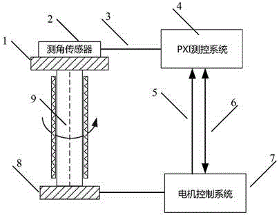
[0024] see figure 1 , which is the structure and components of the dynamic angular position positioning error measurement device targeted by the present invention.

[0025] The dynamic angular position positioning error measuring device of the present invention comprises an angle measuring sensor, a PXI measurement and control system, a motor control system, and a servo motor. Among them, the angle measuring sensor is composed of a spatial four-frequency differential laser gyroscope and its control circuit. The turntable to be tested is connected to the servo motor, and the measuring end is provided with a transition board 1, the angle sensor is installed on the transition board, and connected to the PXI measurement and control system through a flexible cable, which is connected to the motor control system 7 through a signal channel and a data channel , whi...


PUM


Abstract

The invention belongs to the technology of high-precision angle measurement and relates to a device and method for improving the measurement precision of a rotary table dynamic angular position error. The device comprises an angle measurement sensor, a highly-stable external synchronous clock, a servo motor control system, and a servo motor. The angle measurement sensor is formed by a spatial four-frequency differential laser gyroscope and a control circuit thereof. The angle measurement sensor and the servo motor control system of a detected rotary table are synchronized by a highly-stable clock signal. The servo motor control system and the high-precision angle measurement sensor transmit high-speed angular increment information thereof to a PXI measurement and control system. The PXI measurement and control system outputs dynamic angular position error information. By means of a manner that the PXI measurement and control system and a motor control system are deeply coupled, a dozens of MHz synchronizing clock between the PXI measurement and control system and the motor control system, and high-speed phase-locked loop technology, the device and the method control the clock misalignment and clock jitter of the PXI measurement and control system and the motor control system to be a magnitude of nanoseconds, and achieve super-speed and high-precision synchronous measurement of rotating angle dynamic errors.

Description

technical field [0001] The invention belongs to the dynamic error measurement technology of the rotation angle, and relates to a device and a correction method for improving the measurement accuracy of the dynamic angle position error of a turntable. Background technique [0002] Angle measurement is an important part of geometric measurement technology, especially high-precision dynamic angle calibration. For example, in the fields of CNC machine tools, high-precision turntables, satellite antennas, and remote telescopes, there are situations that require both static positioning accuracy and stability. Rotational dynamics, that is, the problem of angular position accuracy at relatively high rates of rotation. Previously, the high-precision measurement of the characteristics of the turntable usually uses an optical code disc or a method based on an autocollimator, but the former has limited accuracy and cannot measure the dynamic characteristics of angular rotation, while th...

Claims


Application Information

Patent Timeline
Patent Type & Authority Applications(China)
IPC IPC(8): G01B21/22
CPCG01C19/64G01C25/005
Inventor 陈林峰王京献傅鑫
Owner FLIGHT AUTOMATIC CONTROL RES INST
Why Eureka
Try Eureka