Sensor and sensing method based on electrostatic induction
An electrostatic induction and sensor technology, applied in the sensor field, can solve the problems of not satisfying energy saving, difficult to work independently for a long time, and the application range of the sensing method is narrow, and achieve the effect of a wide range of applications.
- Summary
- Abstract
- Description
- Claims
- Application Information
AI Technical Summary
Problems solved by technology
Method used
Image

Examples
Embodiment 1
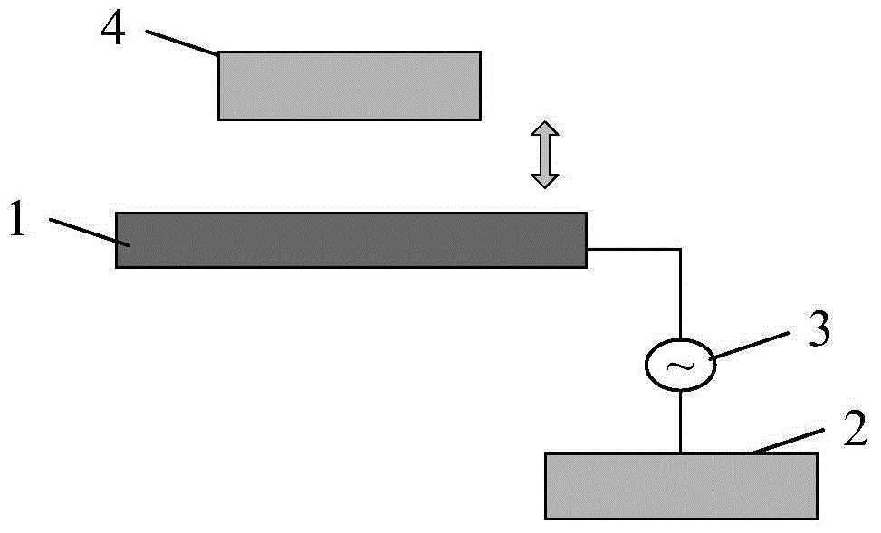
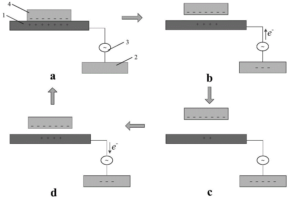
[0056] The typical structure of the sensor based on electrostatic induction provided in this embodiment can be found in figure 1 , the sensor includes a sensing component for sensing the movement of the detected object, wherein the sensing component is composed of a first electrode layer 1 and a second electrode layer 2 matched therewith, the first electrode layer 1 and the The second electrode layer 2 is separated and electrically connected, and the detected object 4 can be separated from the first electrode layer 1 of the sensing component after contacting each other, such as figure 1 As shown by the middle arrow, the movement of the detected object 4 changes the potential of the charge carried by the detected object 4 on the first electrode layer 1, and the charge flows between the first electrode layer and the second electrode layer under the action of electrostatic induction. create a current. Connecting the detection device 3 between the first electrode layer 1 and the ...
Embodiment 2
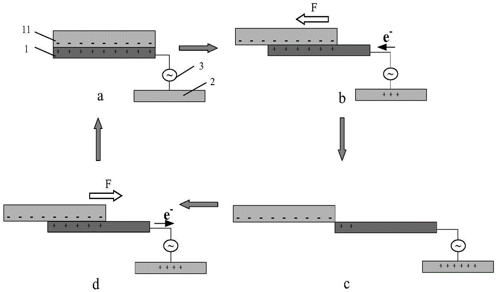
[0085] In the sensor, a friction layer can also be included, and the first electrode layer of the sensing part is pasted on the lower surface of the friction layer, so that the first electrode layer does not directly contact the detected object or other objects, which can protect the sensing part of the sensor . The friction layer of the sensor can be charged or uncharged. Since the relative position of the friction layer and the first electrode layer remains unchanged, when the charged object to be detected moves relative to the first electrode layer, the friction layer will not It has an effect on the charge movement between the first electrode layer and the second electrode layer in the sensing component.
[0086] In this embodiment, the typical structure of the sensor can be found in Figure 6 The sensing components included in the sensor are formed by electrically connecting the first electrode layer 1 and the second electrode layer 2. The friction layer 5 is arranged on...
Embodiment 3
[0098] The sensor provided in Embodiment 1 and Embodiment 2 of the present invention may further include an isolation layer, which is used to isolate the first electrode layer and the second electrode layer of the sensing component, so that the two are separated and maintain a set relative position, and The sensing component can be insulated and isolated from other devices.
[0099] see Figure 7 The first electrode layer 1 and the second electrode layer 2 of the sensing component are all embedded in the isolation layer 6, so that the first electrode layer 1 and the second electrode layer 2 are separated and fixed in relative position, and at least the first electrode layer 1 The upper surface of the exposed isolation layer 6. The upper surface of the second electrode layer 2 may or may not expose the isolation layer 6 . The first electrode layer 1 and the second electrode layer 2 can be electrically connected through wires or conductive films.
[0100] In other embodiments...
PUM
| Property | Measurement | Unit |
|---|---|---|
| Thickness | aaaaa | aaaaa |
Abstract
Description
Claims
Application Information
 - R&D
- Intellectual Property
- Life Sciences
- Materials
- Tech Scout
- Unparalleled Data Quality
- Higher Quality Content
- 60% Fewer Hallucinations
Browse by: Latest US Patents, China's latest patents, Technical Efficacy Thesaurus, Application Domain, Technology Topic, Popular Technical Reports.
© 2025 PatSnap. All rights reserved.Legal|Privacy policy|Modern Slavery Act Transparency Statement|Sitemap|About US| Contact US: help@patsnap.com