Variable integral time non-uniformity correction method based on scenes

A non-uniformity correction and integration time technology, which is applied in image analysis, radiation pyrometry, optical radiation measurement, etc., can solve the problems of large calculation, large storage, and large research workload

Inactive Publication Date: 2015-11-25
NANJING UNIV OF SCI & TECH
View PDF3 Cites 9 Cited by
  • Summary
  • Abstract
  • Description
  • Claims
  • Application Information

AI Technical Summary

Problems solved by technology

The time-domain high-pass filter method suppresses the influence of low-frequency noise on the non-uniformity of the image, overcomes the problem of large storage capacity based on reference element correction, but also requires a good linearity in the detector response rate
The artificial neural network method is to connect each neuron to an array element, and then design a hidden layer. Each neuron of it is connected to several adjacent array elements like a horizontal

Method used


Image

  • Variable integral time non-uniformity correction method based on scenes
  • Variable integral time non-uniformity correction method based on scenes
  • Variable integral time non-uniformity correction method based on scenes

Examples


Embodiment 1

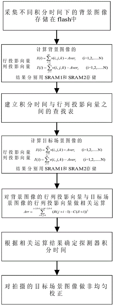
[0055] to combine figure 2 , set the selected background images to be 20, the background images are collected when the integration time of the detector is 1-20ms respectively, increase by 1ms each time, calculate the background images under 20 integration conditions, and correlate the row and column projection vectors Select the constant δ of the row vector displacement offset of the shooting scene image during the operation row is 30, the constant δ of the column vector displacement offset of the shooting scene image col for 30. The size of the image captured by the detector is 256*320.

[0056] The specific implementation process is as follows: firstly, the background images under 20 different integration times are collected by the detector and stored in the flash, and the row projection vectors and column projection vectors of all the background images are obtained respectively by using formulas (5) and (6). And store the projection vector in SRAM, establish a lookup ta...


PUM


Abstract

The invention discloses a variable integral time non-uniformity correction method based on scenes. The method comprises calculating row projection vectors and column projection vectors of background images of a detector under different integral conditions firstly, storing the background row and column projection vectors, and then forming a lookup table. When the detector shoot an image at the different scenes, in order to determine best integral time of the detector, the row and column projection vectors of the image are calculated firstly, related operation respectively between the row and column projection vectors and the background row and column vectors in the lookup table are performed, the most relevant background of the image is found, and the best integral time of the detector is determined through the background. Innovation points of the method are in that the best integral time of the detector in the different scenes can be found, the image obtained under the best integral condition is in favor of subsequent image registration, registration precision is improved, and then the method has the good non-uniformity correction effect.

Description

Technical field: [0001] The invention relates to the field of non-uniformity correction of infrared images, in particular to a scene-based non-uniformity correction method of variable integration time. Background technique: [0002] In the field of infrared imaging, infrared focal plane array has become the development trend of infrared imaging technology. However, due to the limitation of the manufacturing process, the infrared focal plane array has a lot of non-uniformity and the dynamic range of imaging is small. The dynamic range characterizes the range in which the infrared system can detect the size of infrared radiation. With a wider dynamic range, more target information can be obtained, which is beneficial to the analysis and identification of the target. [0003] At present, the widening of the dynamic range of the infrared focal plane array imaging system is mainly realized by adjusting the integration time, but with the change of the integration time, the non-un...

Claims


Application Information

Patent Timeline
IPC IPC(8): G01J5/00G06T7/00
Inventor 隋修宝颜奇欢钱毅涛陈钱顾国华钱惟贤何伟基于雪莲路东明钱佳王晨尹春梅高航孙镱诚曾俊杰李晓帆赵耀沈雪薇刘源
Owner NANJING UNIV OF SCI & TECH
Why Eureka
Try Eureka