Positioning and locating device for radiotherapy and positioning method of dynamic target region

A radiotherapy and positioning device technology, which is applied in radiotherapy, treatment, and radiodiagnostic instruments, etc. It can solve the problems of not being able to directly know the movement characteristics of the target area in the body, low utilization rate of the machine, and slow positioning time. , to achieve the effect of easy image registration, improved application range, and small system error

Active Publication Date: 2015-05-06
RADIATION THERAPY MEDICAL SCI & TECH CO LTD
View PDF3 Cites 38 Cited by
  • Summary
  • Abstract
  • Description
  • Claims
  • Application Information

AI Technical Summary

Problems solved by technology

This accuracy is greatly affected by experience, misoperation and misjudgment, and is not suitable for highly integrated and advanced automated precise radiotherapy systems
[0005] There are also some devices that use the method of placing infrared reflection marks on the patient's body surface, infrared laser irradiation, camera photography, and comparing with the mark position at the initial positioning to perform patient positioning. This positioning method is improved compared with the previous method. However, the positioning time is relatively slow. For the dynamic target area, only the movement information of the patient's body surface can be obtained, and the movement characteristics of the target area in the body cannot be directly known. The utilization rate of the machine is not high, and the positioning and positioning cannot be performed quickly and automatically.

Method used


Image

  • Positioning and locating device for radiotherapy and positioning method of dynamic target region
  • Positioning and locating device for radiotherapy and positioning method of dynamic target region
  • Positioning and locating device for radiotherapy and positioning method of dynamic target region

Examples


Embodiment

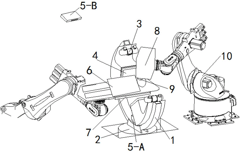
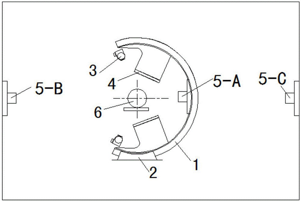
[0039] Such as Figure 1 ~ Figure 2 As shown, a positioning device for radiotherapy includes a dual-image C-arm system, a robot treatment couch 7, a compact linear electron accelerator 8, a secondary collimator 9, and a treatment robot 10. The treatment robot 10 and the dual-image C-arm The position of the system is corresponding, the therapeutic robot 10 has an operating arm, the compact linear electron accelerator 8 is installed at the end of the operating arm of the therapeutic robot 10, and the secondary collimator 9 is installed at the end of the compact linear electron accelerator 8; the robot treatment bed 7 Set up at the corresponding position of the dual-image C-arm system, the C-arm slide rail laser light 5-A is installed inside the dual-image C-arm system, and the left laser light of the C-arm installation space is installed at the corresponding position outside the dual-image C-arm system Light (5-B) and right laser light with respiration tracker mounted above the ...


PUM


Abstract

The invention discloses a positioning and locating device for radiotherapy and a positioning method of a dynamic target region. A therapy robot has an operating arm, wherein a compact linear electronic accelerator is arranged at one end of an operating arm of the therapy robot, and a secondary collimator is installed at one end of the compact linear electronic accelerator; a robot treatment table is arranged on a corresponding position of a double-image C-arm system, an C-arm sliding rail laser locator is arranged inside the double-image C-arm system, and a left side locator for an C-arm installation space is arranged on a corresponding position at the outer part of the double-image C-arm system. The positioning and locating device provided by the invention is provided with two groups of X-ray image systems, so as to realize binocular imaging; when the C-arm sliding rail rotates and a group of X-ray image systems is started, and CBCT (Cone Beam Computed Tomography) imaging can be realized; according to the positioning method, different imaging ways are adopted for a static target region and a dynamic target region, the rapidity and timeliness of the binocular imaging, the high quality, high definition and image registration of the CBCT imaging can be fully exerted.

Description

technical field [0001] The invention relates to the field of medical equipment and its positioning method, in particular to a radiotherapy positioning device and a static and dynamic target area positioning method. Background technique [0002] Radiation therapy is one of the important means of tumor treatment, which is of great significance for improving human health and increasing human life span. Statistics provided by the World Health Organization (WHO) show that among curable cancers, the cure rate of surgery is 22%, the cure rate of radiotherapy combined with surgery is 6%, the cure rate of radiotherapy is 12%, and the cure rate of chemotherapy is only 5%. Visible, radiation therapy is an important technical means of cancer cure. A research report published at the 18th World Health Organization International Anti-Cancer Union Congress stated that the global cancer situation is getting worse, the number of new patients will increase from the current 10 million to 15 mi...

Claims


Application Information

Patent Timeline
Patent Type & Authority Applications(China)
IPC IPC(8): A61N5/00A61B6/03A61B6/00
Inventor 吴大可姚进周付根张兵李超廖华宣韦祟高
Owner RADIATION THERAPY MEDICAL SCI & TECH CO LTD
Why Eureka
Try Eureka