Ink jet printer, printer control unit, printer system including the same, and storage medium with the operation program of the printer control unit stored for controlling double-side printing

a technology of printer control and control unit, which is applied in the direction of digital output to print units, visual presentation using printers, instruments, etc., can solve the problems of irregular waves or curls of printing paper having irregular waves or curls, and the speed of printing paper speed increase, so as to achieve high quality and ease the operation. trouble, the effect of high quality

Inactive Publication Date: 2005-11-17
SEIKO EPSON CORP
View PDF14 Cites 37 Cited by
  • Summary
  • Abstract
  • Description
  • Claims
  • Application Information

AI Technical Summary

Benefits of technology

[0011] Accordingly, the first object of the present invention is to provide technique to print high quality images by an ink jet printer even in the double-side printing job. The second object of the present invention is to allow the ink jet printer that is able to perform double-side printing to print high quality page images in the proper area on both surfaces of a plurality of printing medias successively. The third object of the present invention is to ease the operational trouble which a user encounters when executing double-side printing job by an ink jet printer.
[0016] With this printer control unit, the timing in feeding the printing medias having images printed on the front surfaces that are subject to a timing lag before arriving the print head is adjusted. Consequently, the accuracy of the registration of the printing medias with respect to the print head is improved, so that the image is printed at the proper position of the printing medium.
[0041] With this printer control unit, since a waiting time is provided before feeding the printing medium having an image printed on the front page, printing of the image on the back surface may be started only after ink on the front surface of the printing medium is dried. Therefore, even when the front surface of the printing medium comes into contact with the roller while the printing medium is fed for printing on the back surface, the quality of the page image printed on the front surface of the printing medium is not deteriorated. Therefore, high-quality images may be printed on both surfaces of the printing medium.
[0042] It is also possible to provide detecting means for detecting information on the quantity of ink used for printing the first image which is to be printed ahead of the other one of the pair of images, so that the command issuing means generates a command for delaying the start of feeding the printing medium for printing the second image as long as the period of time corresponding to the waiting time according to information detected by the detecting means on the first image paring with the second image. In such an arrangement, a minimum waiting time required to let ink on the front surface of the printing medium dry is provided so as to prevent the throughput from decreasing. In this case, by reducing the waiting time for the second image in accordance with the period elapsed since finishing the first image paring the second image, the print processing is prevented from taking a long time unnecessarily. This arrangement is effective especially in the case where the printer begins printing the images for the back surfaces of a plurality of printing medias after finishing printing the image for the front surfaces of all of printing medias, since the time required for printing the image on the front surfaces of the following printing medias is counted as the waiting time.
[0043] Alternatively, it is also possible to provide the printer control unit with printing condition storing means in which the waiting times in correspondence with the type of printing medium and the type of ink are stored, so that the command generating means reads the waiting time corresponding to at least one of the type of printing medium on which the second image is printed and the type of ink used for printing the first image paring with the second image from the printing condition storing means, and generates a command for delaying the start of feeding printing medium for the second image as long as the period of time corresponding to the waiting time. In this arrangement, the waiting time can be set according to the characteristics of the printing medium being used and the characteristics of ink being used. In this case, by reducing the waiting time for the second image in accordance with the period elapsed since finishing the first image paring the second image, the print processing is prevented from taking a long time unnecessarily. This arrangement is effective especially in the case where the printer begins printing the images for the back surfaces of a plurality of printing medias after finishing printing the image for the front surfaces of all of printing medias, since the time required for printing the image on the front surfaces of the following printing medias is counted as the waiting time.
[0044] In the case where the printer as a controlled system of the printer control unit is a printer of the type that the advancement of the printing medium fed by the rotation of the feeding roller is suspended by the registering roller located forward of the printing medium, it is also possible to include the instruction for rotating the registering roller in the direction to move the printing media backward and rotating the feeding roller according to the rotation of the registering roller in the paper feed command for delaying the start of feeding the printing medium for printing the second image. In this arrangement, since the printing medium having images on the front surfaces are fed toward the registering roller, but the leading edges thereof are flipped by the reverse rotation of the registering rollers, thus skew of the printing media on the feed is corrected, and consequently the position of the leading edges of the printing media with respect to the print head is registered. Therefore, the image can be printed at the proper position on the back surface of the printing medium having the image printed on the front surface, and thus high-quality image can be printed at the proper position on both surfaces of the printing medium.

Problems solved by technology

In addition, the printing medium having printed a page image on the front surface is subject to irregular waves or curls.
In this way, the printing medium of which increased in weight corresponding to the weight of ink, or the printing paper having irregular waves or curls may not be able to travel smoothly when it is fed in the same condition as the case of the blank printing medium.
Since the printing medium having a page image printed on the front surface thereof contains ink therein and thus the hygroscopicity is deteriorated, it needs longer time to be dried than the blank printing medium.
Therefore, when the page image is printed again on the back surface of the printing medium that is deteriorated in hygroscopicity, the image cannot be dried in a short time as in the case of the blank printing medium.
Therefore, when printing the image on the back surface, the medium cannot be fed as smoothly as the case of printing on the front surface.
When printing of the page image on the back surface is started under such a condition, the page image cannot be printed at the correct area on the back surface of the printing medium.
When it happens, ink on the back surface of each printing medium on the paper receiving tray is transferred to the front surface of another printing medium, thereby deteriorating the quality of the page image for both surfaces of each printing medium on the paper receiving tray.
However, it is troublesome for users because it requires the repeated operations that are not necessary in the normal one-side printing.

Method used


Image

  • Ink jet printer, printer control unit, printer system including the same, and storage medium with the operation program of the printer control unit stored for controlling double-side printing
  • Ink jet printer, printer control unit, printer system including the same, and storage medium with the operation program of the printer control unit stored for controlling double-side printing
  • Ink jet printer, printer control unit, printer system including the same, and storage medium with the operation program of the printer control unit stored for controlling double-side printing

Examples


first embodiment

[0153] First of all, a structure of a printing system according to the present invention will be described. What is shown here is a structure of the system including a printer that is able to print on both surfaces of printing media such as a cut sheet paper by reversing the sheets manually by the user.

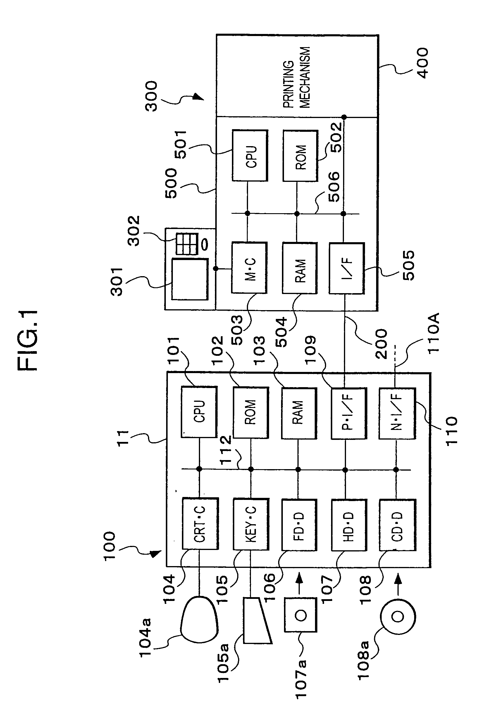
[0154] The printing system according to this embodiment comprises, as shown in FIG. 1, a host 100, a printer 300, a cable 200 connecting between the host 100 and the printer 300.

[0155] The host 100 has a hard ware structure as a normal information processor. More specifically, an enclosure includes a Central Processing Unit (CPU) 101, a Read-only Memory (ROM) 102, a random-access RAM 103, a display controller 104, a keyboard controller 105, a floppy disk drive 106, hard disk 107, CD-ROM drive 108, a printer interface 109 to which a cable 200 is connected, a network interface 110 to be connected to the communication line 110a as needed, and a bus 112 for transmitting data therebetween...

second embodiment

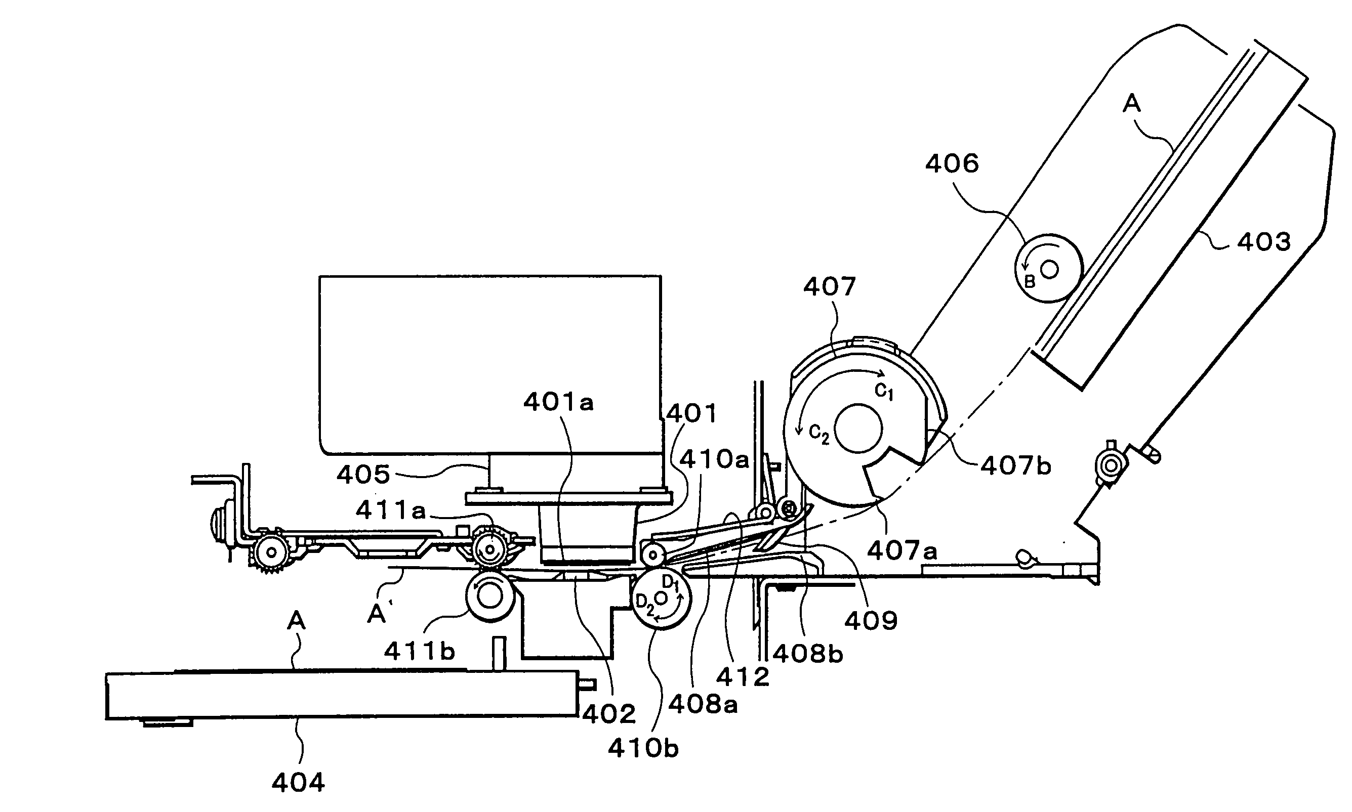
[0194] However, the construction of the ink jet printer of the present invention does not have to be as described so far. For example, it is also possible to arrange so that the length of the waiting time and the speed of rotation of the upper and lower registering rollers 410a, 410b and the feeding roller 407 can be controlled according to the quantity of ink attached on the cut paper having the image already printed on the front surface. Such an arrangement will now be described as the present invention.

[0195] In this arrangement, as shown in FIG. 7, the host 100′ further comprises an ink quantity detecting section 158 and a paper feed condition storing section 159 in addition to the functional structures described above (See FIG. 2). These novel functional structures are implemented by the hardware structure (See FIG. 1) as in the case of the host 100 described above and a program and data stored in the memory.

[0196] The paper feed condition storing section 159 includes a waitin...

third embodiment

[0231] the present invention will now be described.

[0232] The printer system according to this embodiment comprises a printer host 100″, a printer 300″ for printing based on the printing command supplied from the printer host 100″, and a cable 200″ connecting between the host 100″ and the printer 300″, as shown in FIG. 14.

[0233] In this embodiment, the host 100″ has a hardware structure as a normal information processor as in the case of the host 100 in the first embodiment, described above. In other words, the enclosure 11 of the host 100″ includes a CPU 101″ for executing various programs, a ROM 102″ having various control programs in advance, a RAM 103, a display controller 104″ for controlling the display unit, a keyboard controller 105″ for controlling the keyboard, a floppy disk drive 106″, hard disk 107″, CD-ROM drive 108″, a printer interface 109″ to which a cable 200″ is connected, a network interface 110″ to be connected to the communication line 110a″ as needed, and a bu...


PUM

PropertyMeasurementUnit
rotational speedaaaaaaaaaa
timeaaaaaaaaaa
weightaaaaaaaaaa

Abstract

An ink jet printer with a double-side printing function enables to print page images at a proper position on both surfaces of a cut paper, is provided. When feeding the cut paper A having an image printed on the front surface, the feeding roller 407 is rotated in the direction C1 to feed the cut paper A and simultaneously the registering rollers 410a, 410b are rotated in the direction D1 to push back the cut paper. In addition, the double-side printing is easily realized in both of the cases where the ink jet printer with the double-side printing function is connected to the host, and where the ink jet printer without double-side printing function is connected to the host by having the host make an inquiry of the printer whether or not double-side printing is available (step 6). Based on the results of the inquiry, printing commands are generated and sent to the printer.

Description

BACKGROUND OF THE INVENTION [0001] 1. Field of the Invention [0002] The present invention relates to an image recording technique and, more specifically, to an ink jet printer which lends itself to use for double-side printing, and to the technique for controlling the ink jet printer. [0003] 2. Description of Related Art [0004] An ink jet printer disclosed in Japanese Patent Laid-Open No. 9-254376 is known as a printer that is able to print images on both surfaces of a printing medium. When double-side printing mode is designated in this ink jet printer, a printing medium in the paper-feeding cassette is fed between a print head and a platen, passed therethrough, moved backward again, and then fed again between the print head and the platen from the same side. During such an automatic feeding operation, an image for the odd-numbered page is printed on one surface of the printing medium, and then an image for the even-numbered page is printed on the other surface of the printing medi...

Claims


Application Information

Patent Timeline
Patent Type & Authority Applications(United States)
IPC IPC(8): G06F3/12G06K15/00G06K15/02G06K15/10G06K15/16
CPCB65H9/006B65H2301/512125B65H2404/7231G06F3/1204G06F3/1205G06F3/1253G06K2215/0088G06K15/00G06K15/02G06K15/102G06K15/16G06K2215/0017G06F3/1284
Inventor NAKAJIMA, HISANORIMOMOSE, HIROAKI
Owner SEIKO EPSON CORP
Why Eureka
Try Eureka