
Card access device

A card access and card technology, applied in the field of bank self-service equipment, can solve the problems of inability to handle new cards, inability to conveniently retrieve original cards, etc., and achieve the effects of improving bank work efficiency, occupying less space and lowering manufacturing costs.

Inactive Publication Date: 2015-11-25
CHINA ELECTRONICS GREAT WALL CHANGSHA INFORMATION TECH +1
View PDF5 Cites 6 Cited by
  • Summary
  • Abstract
  • Description
  • Claims
  • Application Information

AI Technical Summary

Problems solved by technology

[0004] Furthermore, with the requirement of switching from magnetic stripe cards to chip cards in my country, when customers need to replace new cards, banks will recycle old cards, so equipment is required to temporarily store the original old cards in the self-service return card In the module, when the card production fails for some reason, the customer can choose to get back the original old card, without causing complaints that the customer can neither apply for a new card nor conveniently get back the original card

Method used


Image

  • Card access device
  • Card access device
  • Card access device

Examples


Embodiment 1

[0071] Such as Figure 11 As shown, the card access device 01 is arranged behind the card reader 02, and its bayonet is directly opposite to the bayonet inlet at the tail of the card reader 02. It is installed on the bracket 03 and can be used in financial self-service terminals such as ATM equipment. Entering a wrong password for the first time, or when the user fails to get back his card 7 within a predetermined time due to negligence, etc., causing the card 7 to be swallowed, the card reader 02 will return the card 7 to be swallowed to the card access device 01 A specified temporary storage unit.

[0072] With the receipt, password or valid ID card, the user can issue the temporarily stored card access device 01 directly to the customer without having to be returned to the user by the counter staff, which can effectively improve the cardholder's ability to retrieve the swallowed card. speed.

[0073] When the card 7 has not been retrieved by the user beyond a certain peri...

Embodiment 2

[0075] Such as Figure 12 As shown, the card access device 01 is arranged in the self-service card issuing equipment. When the customer needs to change the card (such as replacing the magnetic stripe card with a chip card), the old card can be temporarily stored in the card access device 01 first. 7. When the issuance is unsuccessful, the original card can also be returned to the customer, which can effectively solve the bank card issuance and bank card return processing procedures, improve bank work efficiency, reduce bank maintenance costs, enhance customer experience, and effectively eliminate customer complaints. In addition, because some customers are not fully familiar with the self-service card issuance business process at present, the bank cards that should be issued to customers are not issued to customers according to the established process, but due to customer negligence, the card issuing module swallowed them because they were not picked up within the time limit. ...


PUM


Abstract

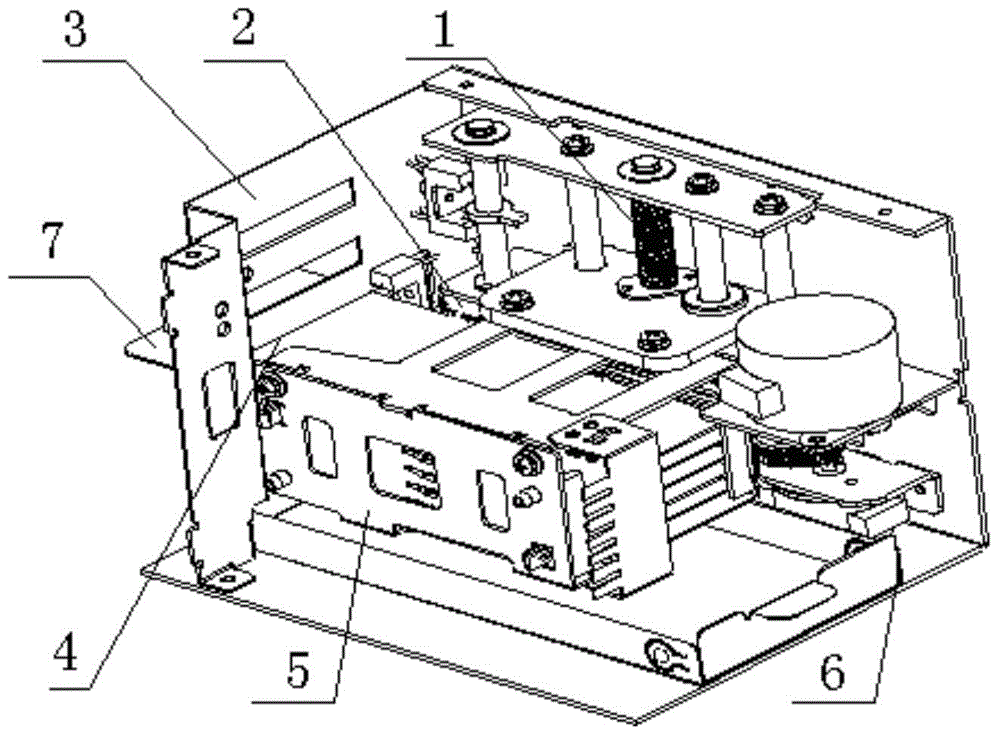
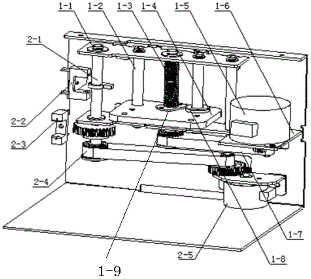
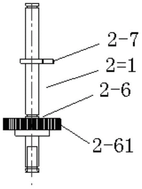
The invention discloses a card access device. The card access device comprises a shell (3), a temporary storage bin (5), a card lifting mechanism (1), a card horizontal conveying device (2), a corresponding detection device and a main control panel; a front cover plate of the shell (3) is provided with a first bayonet (4) used for allowing a card to enter or exit, the temporary storage bin (5) is provided with multiple temporary storage units used for recycling and sending out cards, the card lifting mechanism (1) is installed in the shell (3), the temporary storage bin (5) is fixedly connected to the card lifting mechanism (1), and the card horizontal conveying device (2) is installed on the portion, located between the temporary storage bin (5) and the first bayonet (4), of the interior of the shell (3). The card access device can replace bank staff to take the cards and return the cards back to customers, the work efficiency of banks is greatly improved, and the labor cost is reduced.

Description

technical field [0001] The invention relates to bank self-service equipment, in particular to a card access device. Background technique [0002] In the existing ATM equipment, when the user enters the wrong password many times, or when the user fails to retrieve his card within the set time due to carelessness, etc., the card will be swallowed to prevent illegal operations by others. , to ensure the security of the user's card. [0003] In the existing ATM equipment, the bank staff usually collects the swallowed cards periodically, and then the cardholder goes to the bank counter to collect them with a valid identity certificate, and the counter staff returns them to the user. Generally speaking, the cycle of card return takes 2-7 days, which causes great inconvenience to cardholders. In addition, there are already financial self-service terminals for self-service issuance of bank cards, but because some customers are not fully familiar with the self-service card issuance...

Claims


Application Information

Patent Timeline
IPC IPC(8): G07F19/00
Inventor 孙欣潘桐徐春海刘星美
Owner CHINA ELECTRONICS GREAT WALL CHANGSHA INFORMATION TECH
Learn More