Eureka AIR delivers breakthrough ideas for toughest innovation challenges, trusted by R&D personnel around the world.

Distribution automation cabinet and application thereof

A technology of automation cabinets and cabinets, applied in electrical components, pull-out switch cabinets, substation/switch layout details, etc., can solve problems such as inability to achieve high standardization and modularization, no improvement in structure, and improvement in the structure of automated intelligent terminals , to improve the versatility and exchange rate, facilitate safe operation and management, and improve the efficiency of maintenance and repair.

Active Publication Date: 2015-11-25
袁茂银
View PDF7 Cites 9 Cited by
  • Summary
  • Abstract
  • Description
  • Claims
  • Application Information

AI Technical Summary

Problems solved by technology

Therefore, only by improving the standardization and modularization of equipment can the commonality and interchangeability be improved. However, these manufacturers and the equipment in use have a long history, and cannot achieve high standardization and modularization for a while.
In the prior art, some improvements have been made to the outdoor switchgear and even the distribution automation cabinet: for example, CN202509989 discloses an outdoor switchgear, only a simple structural improvement is made for its door, and the original folding door is changed to a left and right one. Sliding door; as the Chinese patent CN103715616 discloses a ring network cabinet, the overall design of the ring network cabinet is simplified to simplify the internal wiring and reduce the installation workload, and it is not opposite to the inside of the microcomputer protection and control module at the top of the ring network cabinet The structure is improved; for example, Chinese patent CN203367797 discloses an intelligent power distribution automation terminal box, which divides the automation terminal box into a primary room and a secondary room with upper and lower structures, and it is still difficult to confirm the failure of the automation terminal box, resulting in difficulties in maintenance; such as the Chinese patent CN202997354 discloses a distribution network automation ring network cabinet, which includes several ring network cabinets, DTU cabinets and communication cabinets, but the structures in the DTU cabinets and communication cabinets are not improved; as Chinese patent CN103579946 discloses a The distribution network automation integrated ring network cabinet integrates the distribution network automation intelligent terminal and switchgear, but does not improve the structure of the automation intelligent terminal
[0007] To sum up, in the prior art, the improvement of the outdoor switching station, especially the distribution automation cabinet, is nothing more than improving the connection mode of the line, or only improving a certain part for simple structural improvement, which does not reduce the power failure. Fundamentally improved in terms of area and reduced power outage time
[0008] In addition, as the country standardizes the power industry, all power equipment must meet the national grid standards; but at present, because the manufacturers of power equipment are different, the power equipment produced is also different, resulting in With the development of the national grid, the national grid standards have been unified, so all manufacturers must transform the switch stations that have been put into use in accordance with the national grid standards, that is, rearrange the wiring of all equipment in the outdoor switch stations, which is equivalent to The equipment was pulled back to the factory for re-production, which brought certain difficulties to the unification of the national grid standards, and did not fundamentally solve the national grid's transformation requirements for distribution network automation

Method used


Image

  • Distribution automation cabinet and application thereof
  • Distribution automation cabinet and application thereof
  • Distribution automation cabinet and application thereof

Examples


Embodiment Construction

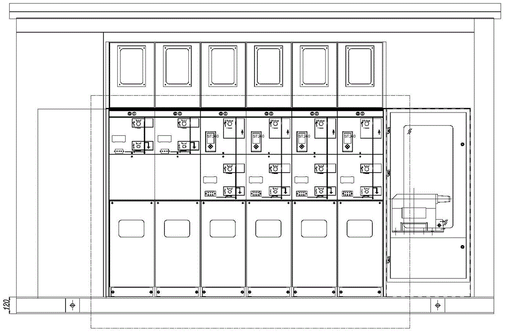
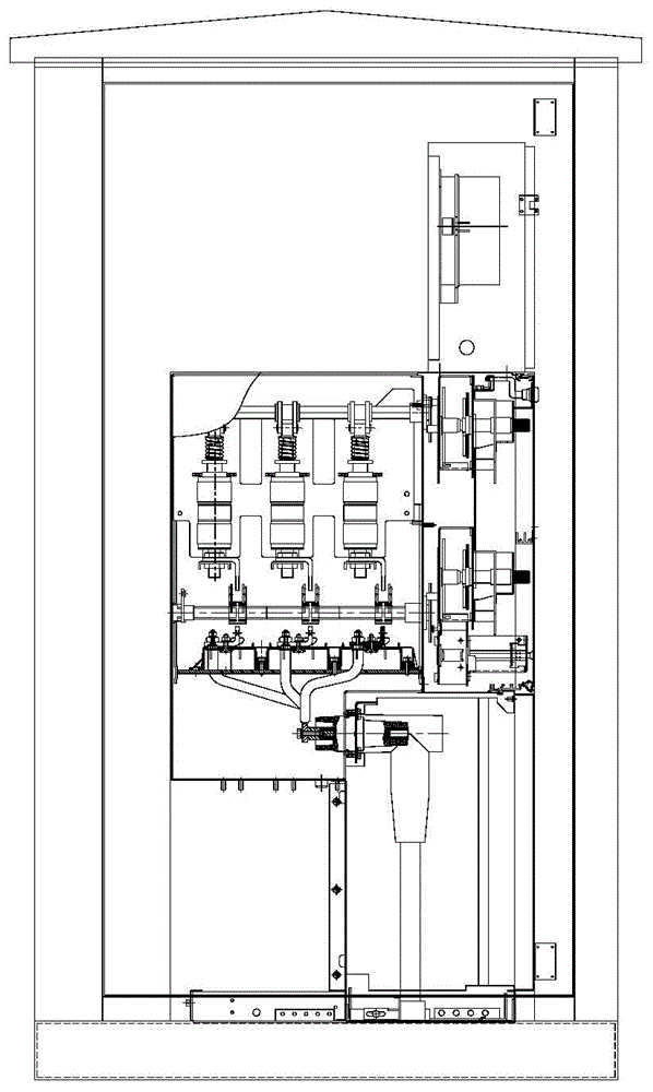
[0069] Taking the application of the distribution automation cabinet in the outdoor switching station as an example, the present invention will be further described in detail and completely in combination with the embodiments and accompanying drawings.

[0070] The types of equipment or components that are not described in detail in the following examples can be commercially available in the prior art, and only need to meet the functions of the distribution automation cabinet provided by the present invention, which is not a limitation of the present invention choose.

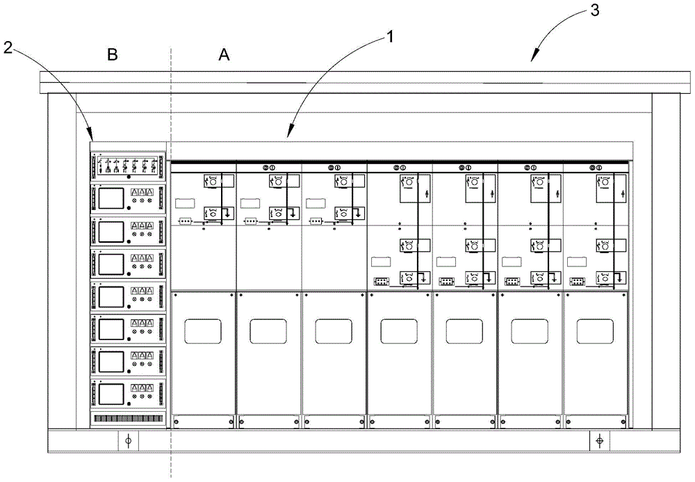
[0071] image 3 with Figure 4 It is the front view and top view of the outdoor shelter, such as image 3 As shown, the outdoor switchgear is divided into two functional areas, a ring network cabinet group 1 formed by setting up several ring network cabinets side by side (that is, the primary equipment area or the incoming and outgoing line area A) and a power distribution automation cabinet 2 (namely The se...


PUM


Abstract

The present invention discloses a distribution automation cabinet including a cabinet body and a plurality of drawer type cabinets. The cabinet body movably connects with the drawer type cabinets, and the drawer type cabinets are arranged in the cabinet body. The distribution automation cabinet is provided with a plurality of functional modules, and the functional modules are assembled in the distribution automation cabinet in a drawer manner for forming drawer unit modules. Compared with the prior art, the distribution automation cabinet provided by the present invention can be used as a standardized product for production, and various functional module equipment in the distribution automation cabinet can also be used as standardized products for production so as to match with any one ring network cabinet group provided by the prior art or available in the market. And the distribution automation cabinet significantly solves a security problem of outdoor opening and closing existed in the prior art, simultaneously, enhances supply electricity continuity of an outdoor opening and closing place, facilitates the development and management of smart power grids of our country, and therefore, the distribution automation cabinet has a wide application prospect.

Description

technical field [0001] The invention relates to a power distribution automation system, more specifically, to a power distribution automation cabinet and its application, and belongs to the technical field of electrical equipment automation. Background technique [0002] The power system includes several main links of power generation, power transmission, power transformation, and power distribution, among which power distribution is a function that directly faces power users. In my country, the situation of "emphasis on power generation, light supply, and no use" has been formed for a long time. The distribution network system is seriously backward, resulting in high loss of residential wires, low voltage, and unreliable power supply, which has become a bottleneck in the power supply and consumption of the power system. In the early stage of power grid construction, more attention was paid to power generation and transmission, while power distribution and power consumption ...

Claims


Application Information

Patent Timeline
Patent Type & Authority Applications(China)
IPC IPC(8): H02B11/173
CPCH02B1/308H02B11/173
Inventor 袁茂银
Owner 袁茂银
Why Eureka
Eureka Blog
Learn More