LED drive circuit

A LED driving and driving current technology, applied in the electronic field, can solve the problems of high production cost, unfavorable integration, and bulky volume, and achieve the effects of low production cost, low volume, and small peripheral devices

Active Publication Date: 2015-11-25
SILERGY SEMICON TECH (HANGZHOU) CO LTD
View PDF5 Cites 10 Cited by
  • Summary
  • Abstract
  • Description
  • Claims
  • Application Information

AI Technical Summary

Problems solved by technology

[0004] It can be seen from the above that the implementation of this LED drive circuit in the prior art requires an independent constant current drive circuit to drive the LED light strings of the corresponding color, and each constant current drive circuit needs to be equipped with a constant current drive control circuit. Such an implementation method, The circuit structure is too complex
In addition, since the constant current drive circuit is usually built with many devices such as energy storage components, the realization of this dimming and color adjustment circuit requires many electronic components, the production cost is high, and the volume of the system is very large. bulky, not conducive to integration

Method used


Image

  • LED drive circuit
  • LED drive circuit
  • LED drive circuit

Examples


Embodiment Construction

[0030] Several preferred embodiments of the present invention will be described in detail below with reference to the accompanying drawings, but the present invention is not limited to these embodiments. The present invention covers any alternatives, modifications, equivalent methods and schemes made on the spirit and scope of the present invention. In order to provide the public with a thorough understanding of the present invention, specific details are set forth in the following preferred embodiments of the present invention, but those skilled in the art can fully understand the present invention without the description of these details.

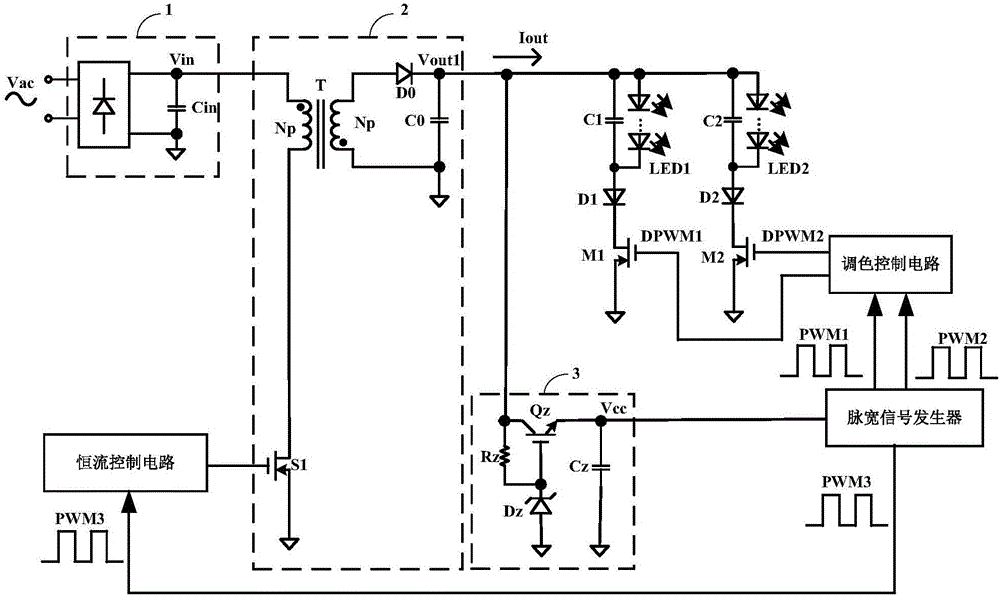
[0031] refer to figure 2 This is a circuit block diagram of an LED driving circuit according to the present invention, the LED driving circuit is used to drive an LED light string group composed of N LED light strings, N is a positive integer not less than 2, and the LED driving The circuit includes a power converter, a color adjustment...


PUM


Abstract

The invention provides an LED drive circuit. A power converter provides constant drive current to an LED lamp string group, a toning control circuit generates a group of switching control signals according to a group of toning pulse width signals generated by a pulse width signal generator, and the switching control signals are used for controlling the switching state of a control switch group serially connected with the LED lamp string group, so as to adjust the proportion of the current of each LED lamp string in the LED lamp string group in the drive current to adjust the color temperature of the LED lamp string group. In addition, a dimming pulse width signal output by the pulse width signal generator can be used for driving a constant current control circuit to adjust the size of the drive current to achieve a dimming function. Therefore, in the LED drive circuit, each LED lamp string does not need to be provided with an independent constant current drive circuit and a constant current control circuit to achieve toning and dimming, the circuit structure is relatively simple and is easy to integrate, the used peripheral devices are smaller, the volume is small and the production cost is low.

Description

technical field [0001] The invention relates to the field of electronic technology, in particular to an LED driving circuit. Background technique [0002] As a new type of lighting tool, LED lighting has the advantages of high light efficiency, long life, and environmental protection, so it is more and more widely used in various lighting fields. There are two ways of LED dimming: DC dimming and PWM dimming. Since PWM dimming has the advantages of constant light color and better stability at low brightness, it is widely adopted by those skilled in the art. [0003] For some special light source environments, not only the brightness of the LED lamps needs to be adjusted, but also the color temperature of the LED lamps needs to be adjusted. refer to figure 1 , shows an LED driving circuit using the prior art. In this implementation, the AC voltage Vac outputs the voltage Vin after passing through the rectification and filtering circuit 01, and the power converter 02 receiv...

Claims


Application Information

Patent Timeline
Patent Type & Authority Applications(China)
IPC IPC(8): H05B37/02H05B44/00
CPCH05B45/46H05B45/20Y02B20/30H05B45/382
Inventor 王建新赖洪斌陈伟
Owner SILERGY SEMICON TECH (HANGZHOU) CO LTD
Why Eureka
Try Eureka