Power supply transformer

A technology for power transformers and casings, applied in transformers, fixed transformers, transformer/inductor casings, etc., can solve problems such as high prices and high manufacturing costs, and achieve the effects of preventing contact, easy assembly, and superior economy

Inactive Publication Date: 2015-11-25
FDK CORP
View PDF8 Cites 1 Cited by
  • Summary
  • Abstract
  • Description
  • Claims
  • Application Information

AI Technical Summary

Problems solved by technology

[0003] As such a wire with a large cross-sectional area, a structure in which a flat wire is used and wound edgewise to form a coil as seen in the following Patent Document 1 has also been proposed, but it is expensive, so there are Problems that lead to increase in manufacturing cost

Method used


Image

  • Power supply transformer
  • Power supply transformer
  • Power supply transformer

Examples


Embodiment Construction

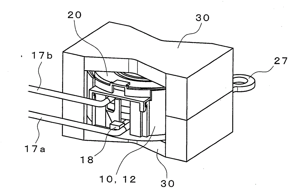
[0034] Figure 1~Figure 6 An embodiment of the power transformer of the present invention is shown, and the reference numeral 10 in the figure is a housing.

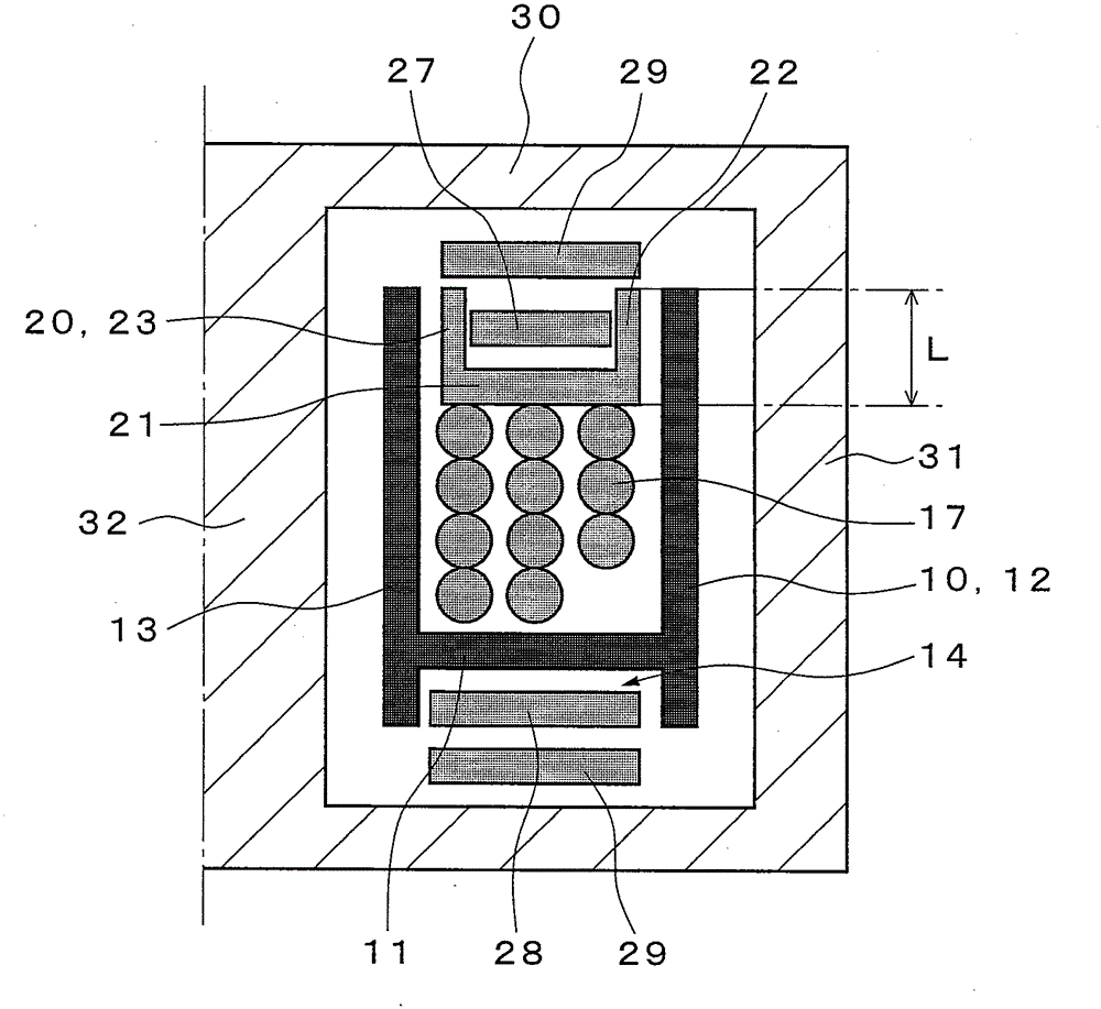
[0035] The casing 10 is made of a disc-shaped bottom plate 11, an outer cylinder 12 erected on the outer periphery of the bottom plate 11, and an inner cylinder 13 erected in a hole formed in the center of the bottom plate 11, and is made of insulating synthetic resin. An integrally formed double-layer cylindrical casing with a bottom.

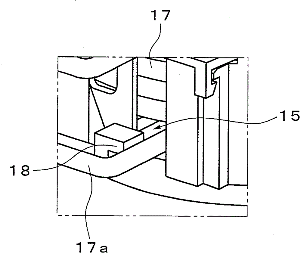
[0036] Here, the outer cylinder 12 and the inner cylinder 13 of the casing 10 are formed to protrude downward compared with the bottom plate 11, thereby forming a concave portion 14 on the back side of the bottom plate 11 (see Image 6 ). Further, a notch 15 extending from the upper opening to the bottom plate 11 is formed in the outer cylinder 11 , and a groove (guide portion) 16 opening at the notch 15 is formed in the bottom plate 11 . Then, the first coil 17 is accommodated betwee...


PUM


Abstract

The present invention provides a highly cost-effective power supply transformer that is easily assembled and capable of ensuring a desired creeping distance between coils, while presenting no concern over insulation breakdown when a voltage is applied. The power supply transformer is provided with a case (10), a first coil (17), a lid body (20), a second coil (27), and a core (30). The case (10) describes the shape of a bottomed double-layered tube. The first coil (17) is accommodated between an inner tube (13) and an outer tube (12) of the case (10). The lid body (20) closes an upper opening of the case (10). The second coil (27) is disposed on a top surface of the lid body (20). The core (30) surrounds the case (10) and the second coil (27). The first coil (17) is made of a solid copper wire alone, the solid copper wire being wound in multiple layers. The lid body (20) is provided with a tubular inner wall section (23) and outer wall section (22) in a flat plate section (21). The second coil (27) is mounted on the flat plate section (21), and the inner wall section (23) and the outer wall section (22) surround the inner circumference and outer circumference of the second coil (27). A guide section (16) is formed on a bottom plate (11) of the case (10), the guide section (16) guiding an end section (17a) of the first coil (17) on the bottom plate side toward the outer tube side. A notch section (15) is formed on the outer tube (12), the notch section being intended to extract the end section (17a) to the exterior.

Description

technical field [0001] The present invention relates to a power transformer suitable for use in power supply circuits of various devices with high current specifications. Background technique [0002] Generally, in a transformer in which a large current flows through a coil, it is necessary to use a wire having a large cross-sectional area in order to reduce the resistance value of the coil and suppress heat generation. [0003] As such a wire with a large cross-sectional area, a structure in which a flat wire is used and wound edgewise to form a coil has been proposed as seen in the following Patent Document 1, but it is expensive, so there are This causes a problem of an increase in manufacturing cost. [0004] Therefore, in the past, many uses such as Figure 7 The transformer shown in the figure is a combination of a coil using a large-diameter round wire and a copper plate pierced into an open loop. [0005] In this transformer, a coil 2 of a thick round wire is wound...

Claims


Application Information

Patent Timeline
Patent Type & Authority Applications(China)
IPC IPC(8): H01F27/32H01F30/00
CPCH01F30/00H01F27/29H01F27/325H01F27/2866H01F27/324H01F27/02H01F27/2823
Inventor 金子幸司秋山英之铃木贵之大田智嗣
Owner FDK CORP
Why Eureka
Try Eureka