
Novel rotary blade

A rotary tiller and a new type of technology, applied in the field of new rotary tillers, can solve the problems of inconvenient tool change, easy breakage, easy deformation of the rotary tiller, etc., and achieve the effects of long service life, not easy to break, and good effect.

Inactive Publication Date: 2015-12-02
哈尔滨市金马农机配件制造有限公司
View PDF4 Cites 2 Cited by
  • Summary
  • Abstract
  • Description
  • Claims
  • Application Information

AI Technical Summary

Problems solved by technology

[0004] The purpose of this invention is to provide a new type of rotary tiller, which solves the problems that the existing rotary tiller is easy to deform, easy to break, and inconvenient to change the knife

Method used


Image

  • Novel rotary blade
  • Novel rotary blade

Examples


Embodiment 1

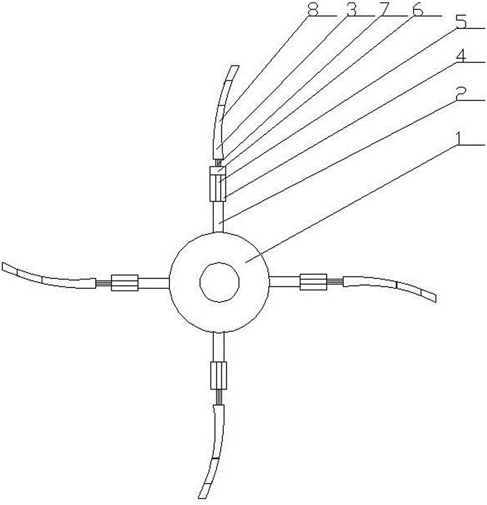
[0020] A new type of rotary tiller, comprising a rotating shaft 1, a fixed cutter shaft 2, and a rotary tiller head 3, four fixed cutter shafts 2 are welded on the rotary shaft 1, and the other end of the fixed cutter shaft 2 is connected to A hydraulic bushing 4 , the hydraulic bushing 4 is internally connected to a hydraulic shaft 5 , and the other end of the hydraulic shaft 5 is welded to the rotary tiller head 3 .

Embodiment 2

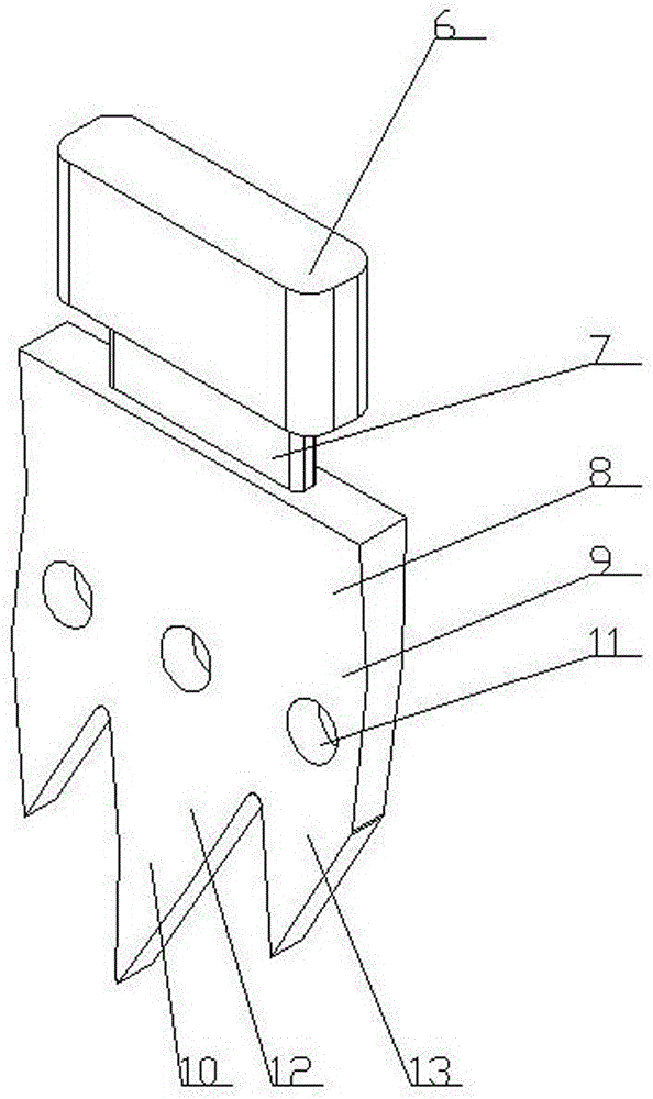
[0022] The rotary tiller head 3 is composed of a welding head 6 , a connecting plate 7 and a cutter body 8 .

Embodiment 3

[0024] The welding head 6 is a cylindrical welding head.


PUM


Abstract

The invention provides a novel rotary blade which comprises a rotating shaft, fixed knife shafts and rotary tillage tool bits. Four fixed knife shafts are welded to the rotating shaft. The other ends of the fixed knife shafts are connected with hydraulic sleeves. The hydraulic sleeves are internally connected with hydraulic shafts, and the rotary tillage tool bits are welded to the other ends of the hydraulic shafts. The novel rotary blade is higher in hardness, greater in strength, not prone to deformation and breakage, longer in service life and better in ploughing effect and solves the problems that an existing rotary blade is prone to being deformed and broken and short in service life, and tool changing is inconvenient.

Description

technical field [0001] The invention relates to the field of agricultural machinery, in particular to a novel rotary tiller. Background technique [0002] Rotary tiller is currently the most used mechanical equipment for farming and land preparation in rural areas. It has the operation effect of plow and harrow in one. Rotary tillage can achieve the effect of soil fragmentation and leveling. It can effectively cut off vegetation and mix it with tillage. In the layer, it can also mix chemical fertilizers and pesticides evenly in the soil. It is widely used in most areas of our country and has a good application prospect. [0003] The rotary tiller is one of the important working parts of the rotary tiller. During work, the rotary tiller not only bears the weight of the rotary tiller and drives it to walk, but also constantly contacts, rubs and squeezes the field, and the soil condition of the field Complex and uneven density distribution, so the rotary tiller is the part tha...

Claims


Application Information

Patent Timeline
Patent Type & Authority Applications(China)
IPC IPC(8): A01B33/10A01B33/12
Inventor 不公告发明人
Owner 哈尔滨市金马农机配件制造有限公司
Learn More