A gas grid filter mixer and method

A filtering mixer, filtering method technology, applied in mixing methods, gas and gas/vapor mixing, chemical instruments and methods, etc., can solve the problems of low production efficiency, long time, can not well meet production requirements, etc. Easy to move, small footprint, good filtering effect

Active Publication Date: 2017-04-26
CHONGQING THRIVE CHEM
View PDF5 Cites 0 Cited by
  • Summary
  • Abstract
  • Description
  • Claims
  • Application Information

AI Technical Summary

Problems solved by technology

[0003] However, none of these existing methods can well meet the production requirements, and each has its own shortcomings in production:
[0004] The way of natural diffusion mixing requires a long time to mix fully, which directly leads to low production efficiency;
[0005] In the way of disturbance mixing, the two gases will move in the same direction in the same container or pipeline, and there will be a long parallel movement process. Although the time is shorter than that of natural diffusion mixing, the production efficiency is still relatively low and cannot meet the requirements.

Method used


Image

  • A gas grid filter mixer and method
  • A gas grid filter mixer and method
  • A gas grid filter mixer and method

Examples


Embodiment 1

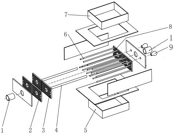
[0030] A gas grid filter mixer, comprising a housing, the interior of the housing is divided into a filter medium distribution chamber and a filter mixing chamber by a partition, a filter medium inlet 1 is arranged on the side wall of the filter medium distribution chamber, and the filter medium The top of the mixing chamber is provided with an inlet 7 for the gas to be filtered, and the outlet 5 for the filtered gas is provided at the bottom. A number of parallel porous nozzles 6 are arranged horizontally in the filter mixing chamber, and the ends of the porous nozzles 6 pass through the partition and enter the filter medium distribution chamber. , both sides of the porous nozzle 6 evenly offer a number of nozzle holes 61.

[0031] A scraper 3 parallel to the partition is also arranged vertically in the filter mixing chamber, and a number of holes for the porous nozzle 6 to traverse are provided on the scraper 3. One side of the scraper 3 is also fixedly connected to the pull ...

Embodiment 2

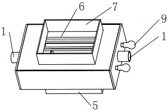
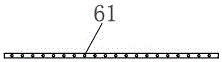
[0035] Such as figure 1 , 2 As shown, a gas grid filter mixer includes a housing, and inside the housing, there are two partitions, a partition 2 and a partition 2 8, which divide the inside of the casing into filter medium distributions from left to right. chamber, filter mixing chamber and filter medium distribution chamber, each filter medium distribution chamber has a filter medium inlet 1 on the side wall, the top of the filter mixing chamber is provided with a gas inlet 7 to be filtered, and the bottom is provided with a filtered gas outlet 5, A number of parallel porous nozzles 6 are arranged horizontally in the filter mixing chamber, and the two ends of the porous nozzles 6 respectively pass through the first partition 2 and the second partition 8 to enter a filter medium distribution chamber. Both sides of the porous nozzle 6 evenly offer some spray holes 61, such as image 3 shown.

[0036] A scraper 3 parallel to the partition is also arranged vertically in the f...

Embodiment 3

[0040] The first step is to set up a filter mixing chamber, in which a number of porous nozzles 6 with several nozzle holes 61 evenly opened on both sides are arranged in a layered and misplaced arrangement, and the ends of the porous nozzles 6 extend outwards out of the filter mixing chamber. room; a scraper 3 is also provided, and each porous nozzle 6 is vertically penetrated in it and can slide, and a pull rod 4 can be used to pull the scraper 3 to slide longitudinally along the porous nozzle 6 outside the filter mixing chamber;

[0041] In the second step, the filter medium is passed into each porous nozzle 6, and enters the filter mixing chamber through the nozzle hole 61 to form a multi-point sieve layout, and the gas to be filtered passes through the filter mixing chamber from the vertical direction, and the gas to be filtered Under the action of angle difference and speed difference, the two different substances with the filter medium move in the shape of "iron flower" ...


PUM


Abstract

The invention discloses a gas grid filter mixer, which comprises a shell, the inside of the shell is divided into a filter medium distribution chamber and a filter mixing chamber by a partition, and a filter medium inlet is arranged on the side wall of the filter medium distribution chamber. The top of the filter mixing chamber is provided with an inlet for the gas to be filtered, and the bottom is provided with an outlet for the filtered gas. A number of parallel porous nozzles are arranged horizontally in the filter mixing chamber, and the ends of the porous nozzles pass through the partition and enter the filter medium. In the distribution chamber, a number of spray holes are evenly opened on both sides of the porous nozzle. The beneficial effects of the present invention are: the filter medium is sprayed into the filter mixing chamber through the porous nozzle to form a multi-point sieve layout, and contacts and mixes with the gas to be filtered; Due to the difference in angle, there is a violent cutting movement between the two non-materials, and an "iron flower"-like airflow is formed at each sieve point, which realizes rapid and sufficient mixing and reaction, and ensures a good filtering effect.

Description

technical field [0001] The invention relates to the technical field of gas treatment, in particular to a gas grid filter mixer and a method thereof. Background technique [0002] When filtering harmful components in gas, it is usually to inject two different gases or gas and liquid into a container or pipeline, let them diffuse and mix naturally, or speed up the mixing by disturbance. [0003] However, none of these existing methods can well meet the production requirements, and each has its own shortcomings in production: [0004] The way of natural diffusion mixing requires a long time to mix fully, which directly leads to low production efficiency; [0005] In the way of disturbance mixing, the two gases will move in the same direction in the same container or pipeline, and there will be a long parallel movement process. Although the time is shorter than that of natural diffusion mixing, the production efficiency is still relatively low and cannot meet the requirements. ...

Claims


Application Information

Patent Timeline
Patent Type & Authority Patents(China)
IPC IPC(8): B01F3/02B01D53/76B01F23/10
Inventor 戴伟
Owner CHONGQING THRIVE CHEM
Why Eureka
Try Eureka