
Continuous hot stamping device and technology

A hot stamping and press technology, applied in the field of continuous hot stamping devices and processes, can solve the problems of long time for hot blank transfer, reduced heating efficiency, surface wear of oxide scale stamping dies, etc., to improve energy utilization and heating efficiency, Avoid the increase of cutting difficulty and ensure the effect of punching and trimming quality

Active Publication Date: 2015-12-02
WUHAN UNIV OF TECH
View PDF10 Cites 36 Cited by
  • Summary
  • Abstract
  • Description
  • Claims
  • Application Information

AI Technical Summary

Problems solved by technology

The existing hot stamping production line has the following problems: First, the ultra-high-strength steel blanks are usually heated in a roller hearth heating furnace, and a large amount of heat will be lost from the roller shaft and the gas, reducing the heating efficiency; second, the blank transfer process not only prolongs the The production cycle, and the hot blank is in contact with the air, the heat loss is serious, and oxidation will occur at the same time (especially for the bare boards that are widely used in China, the oxidation phenomenon is serious), and the oxide skin produced is easy to cause the surface wear of the stamping die; moreover, due to The hot stamped parts after quenching have ultra-high strength and hardness, and laser cutting is usually used in production, which has problems such as long time consumption and high cost
In foreign countries, hot stamping of aluminum alloy plates is also being researched, and there are also problems such as low heating efficiency, long time-consuming transfer of hot blanks, and fast cooling.

Method used


Image

  • Continuous hot stamping device and technology
  • Continuous hot stamping device and technology
  • Continuous hot stamping device and technology

Examples


Embodiment Construction

[0034] In order to make the object, technical solution and advantages of the present invention clearer, the present invention will be further described in detail below in conjunction with the accompanying drawings and embodiments. It should be understood that the specific embodiments described here are only used to explain the present invention, not to limit the present invention.

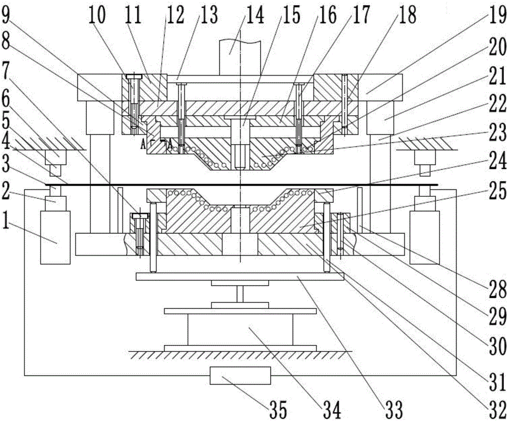
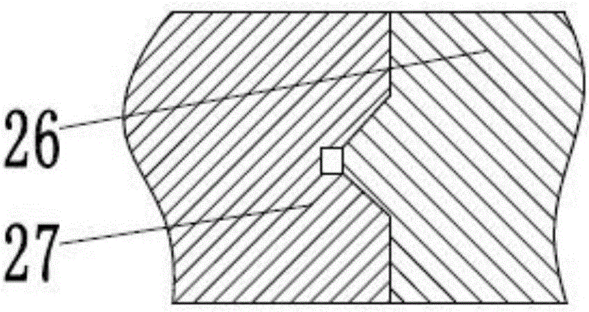
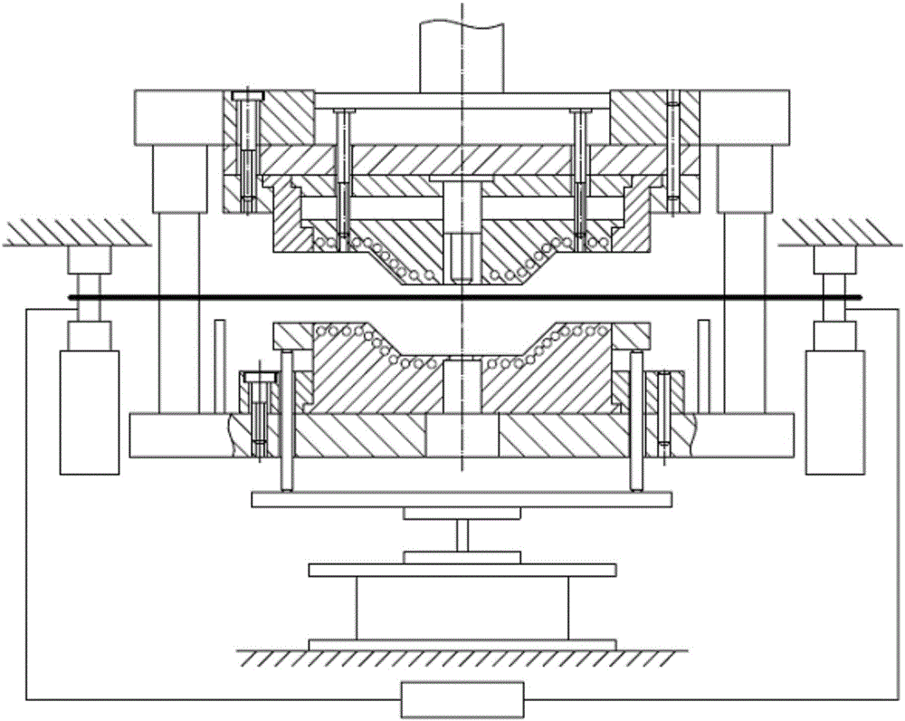
[0035] Such as figure 1 As shown, a continuous hot stamping device, the device includes: a composite mold, and an electric heating mechanism arranged outside the composite mold;

[0036] The composite mold is installed on the double-action press, and the composite mold includes an upper mold and a lower mold that are arranged oppositely; The outer slider 11 of the dynamic press is connected, and the forming punch 23 is slidably installed on the upper die base 19, and is connected with the inner slider 14 of the double-acting press. The forming punch 23 is provided with a cooling system 20, and the...


PUM


Abstract

The invention discloses a continuous hot stamping device and technology. The device comprises a composite die and an electric heating mechanism. The composite die is mounted on a double-action press and comprises an upper die body and a lower die body which are oppositely arranged. The upper die body comprises an upper die base, a forming male die, an edge cutting female die and a piercing male die. The lower die body comprises a lower die base, a forming female die, an ejector plate, an elastic cushion and material supporting racks. The forming female die is fixedly mounted on the lower die base. The ejector plate is arranged under the edge cutting female die. The bottom of the ejector plate is fixedly connected with the elastic cushion through an ejector rod. The material supporting racks are mounted at the two ends of the lower die base. The electric heating mechanism comprises a power source, a movable electrode, a fixed electrode and a lifting assembly. By means of the continuous hot stamping device and technology, fast heating, drawing forming, pressurizing and quenching, edge cutting and piercing can be completed continuously, production efficiency is improved, and the transportation process before a hot blank is stamped is omitted.

Description

technical field [0001] The invention belongs to the technical field of hot stamping, and in particular relates to a continuous hot stamping device and process. Background technique [0002] Hot stamping technology is a new technology for forming lightweight and high-strength parts, which has the advantages of small springback, good mold fit, and high dimensional accuracy. The use of lightweight and high-strength auto parts can improve the safety performance of the car and reduce the weight of the car, which is of great significance for realizing the lightweight of the car. [0003] Traditional hot stamping process: first, heat the prefabricated billet of light-weight and high-strength sheet to a certain temperature, then quickly transfer the hot billet to the mold, and then quickly stamp and form, pressurize and quench to complete the structural transformation, and then take out the hot stamping parts and heat them at room temperature Cool, and finally laser cut to form the...

Claims


Application Information

Patent Timeline
IPC IPC(8): B21D35/00B21D37/10B21D37/16
Inventor 宋燕利华林沈玉含任永强杨龙余成吕祝星
Owner WUHAN UNIV OF TECH
Learn More