Supercharge Your Innovation With Domain-Expert AI Agents!

Self-protected structure for rapidly fixing hydraulic tailstock and rejecting tip

A hydraulic tailstock and tip technology, which is applied in the direction of tailstock/top, tool holder accessories, turning equipment, etc., can solve the problems of tip surface damage, cumbersome operation, and affect production efficiency, so as to increase stability and improve accuracy , the effect of improving stability

Active Publication Date: 2015-12-02
铁王数控机床(苏州)有限公司
View PDF10 Cites 0 Cited by
  • Summary
  • Abstract
  • Description
  • Claims
  • Application Information

AI Technical Summary

Problems solved by technology

[0003] The existing tailstock structure on the market has a relatively complicated structure, and most of them use the push rod to directly hit the tip to withdraw the tip, which will not only cause damage to the surface of the tip, but also generate relatively large noise, and it will be in a noisy working environment for a long time , will have a certain degree of impact on the physical and mental health of employees. At the same time, although the existing tailstock structure can withdraw the top during use, its push rod cannot automatically retreat, so its operation is too It is cumbersome and seriously affects the efficiency of production, so the existing tailstock structure cannot really meet the needs of the current market

Method used


Image

  • Self-protected structure for rapidly fixing hydraulic tailstock and rejecting tip
  • Self-protected structure for rapidly fixing hydraulic tailstock and rejecting tip
  • Self-protected structure for rapidly fixing hydraulic tailstock and rejecting tip

Examples


Embodiment 1

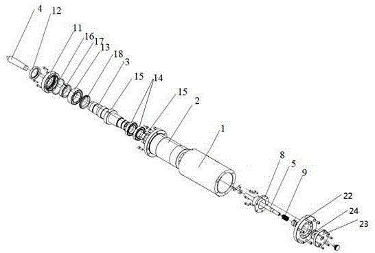
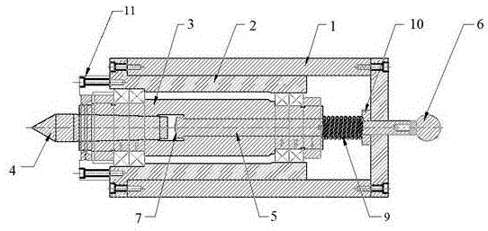
[0023] Such as figure 1 and figure 2 A self-protected quick-fixed hydraulic tailstock retracting top structure is shown, including: tailstock body 1, bushing 2, mandrel 3, top 4, push rod 5 and handle 6, the bushing 2 is composed of a shaft ring and a sleeve, the inner side of the sleeve is stepped, the bearing gland 11 is fixedly connected with the shaft ring through an inner hexagonal screw, and the mandrel 3 is respectively a front shaft and a rear shaft, so Both the front axle and the rear axle are stepped, the middle of the front axle and the rear axle is provided with a mounting groove, and the connecting part of the front axle and the rear axle is provided with a rectangular groove, and the tail of the top 4 and the ends of the push rod 5 are all arranged in the rectangular groove, the mounting groove inside the front axle is inclined from the rectangular groove to the front end, and the inclination of the mounting groove inside the front axle matches the top 4 .

[...

Embodiment 2

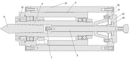
[0029] Such as figure 1 and image 3 A self-protected quick-fixed hydraulic tailstock retracting tip structure is shown, including: tailstock body 1, bushing 2, mandrel 3, tip 4, push rod 5 and handle 6, wherein the The tailstock body 1 is composed of a cylindrical body 21, a bearing sleeve end cover 22 and a tailstock push rod rear guide cover 23.

[0030] The relationship between the above components is as follows:

[0031] The shaft sleeve 2 is composed of a shaft ring and a sleeve, the inner side of the sleeve is stepped, the bearing gland 11 is fixedly connected with the shaft ring by a hexagon socket head screw, and the mandrels 3 are front shafts respectively. and the rear axle, the front axle and the rear axle are stepped, the middle of the front axle and the rear axle is provided with a mounting groove, and the connecting part of the front axle and the rear axle is provided with a rectangular groove, so The tail portion of the top 4 and the end of the push rod 5 ar...


PUM


Abstract

The invention discloses a self-protected structure for rapidly fixing a hydraulic tailstock and rejecting a tip. The self-protected structure for rapidly fixing the hydraulic tailstock and rejecting the tip comprises a tailstock body, a shaft sleeve, a mandrel, the tip, a push rod and a handle, wherein the mandrel comprises a front shaft and a rear shaft, the shaft sleeve is arranged inside the tailstock body, the mandrel is arranged inside the shaft sleeve, and the tip and the push rod are arranged in the middle of the mandrel; a bumper block is arranged at the front end of the push rod which is further provided with a front guide disk and a spring, and the handle is arranged on the tail portion of the tailstock body. According to the self-protected structure for rapidly fixing the hydraulic tailstock and rejecting the tip, the structure is simple, and the operation is convenient; the handle is additionally arranged to push the push rod, the push rod can push out the tip easily, and the push rod can reset automatically by means of the design of the spring on tail portion of the push rod; meanwhile, the bumper block is arranged on one end of the push rod, noise caused by collision of the push rod and the tip can be effectively reduced, the friction between the push rod and the tip can be reduced, and a good protective effect on the surfaces of the push rod and the tip is achieved; therefore, demands of current markets are better met.

Description

technical field [0001] The invention relates to a top structure, in particular to a fast fixed hydraulic tailstock retracting top structure with self-protection. Background technique [0002] With the rapid development of modern society, the upgrading of new products and new technologies is also gradually accelerating, thus putting forward higher requirements for the variety, machining accuracy and efficiency of machine tools. In today's world, all countries attach great importance to the machine tool industry, and are competing to develop mechatronics, high-quality, high-precision, and high-efficiency automated machine tools to accelerate the development of their own industries and national economies. The tailstock structure is an important part of the CNC machine tool, which directly affects the operation of the entire machine tool. [0003] The existing tailstock structure on the market has a relatively complicated structure, and most of them use the push rod to directly...

Claims


Application Information

Patent Timeline
IPC IPC(8): B23B23/04B23B25/04
CPCB23B23/04B23B25/04
Inventor 王磊
Owner 铁王数控机床(苏州)有限公司
Features
  • R&D
  • Intellectual Property
  • Life Sciences
  • Materials
  • Tech Scout
  • Unparalleled Data Quality
  • Higher Quality Content
  • 60% Fewer Hallucinations
Learn More