Hydraulic winch with pneumatic clutch

A hydraulic winch and clutch technology, applied in the field of hydraulic winches, can solve the problems of complex clutch structure, insufficient compactness, unfavorable running stability, etc., and achieve the effects of good running stability, compact structure, and guaranteeing power transmission requirements.

Active Publication Date: 2017-08-04
INI HYDRAULIC
View PDF1 Cites 0 Cited by
  • Summary
  • Abstract
  • Description
  • Claims
  • Application Information

AI Technical Summary

Problems solved by technology

[0004] The purpose of the present invention is to provide a hydraulic winch with a pneumatic clutch with a simple structure, easy processing, good compactness and stable transmission in view of the problems of the existing hydraulic winch with complex clutch structure, unfavorable operation stability and not compact enough

Method used


Image

  • Hydraulic winch with pneumatic clutch
  • Hydraulic winch with pneumatic clutch
  • Hydraulic winch with pneumatic clutch

Examples


Embodiment

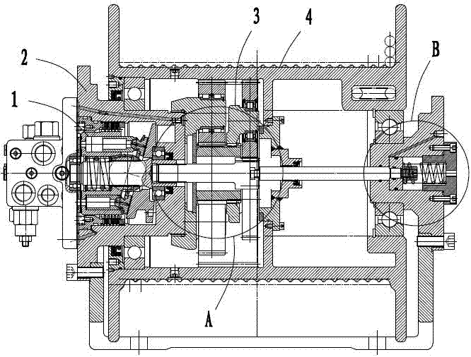
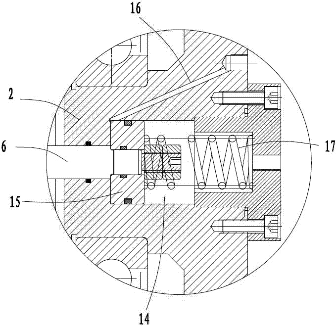
[0025] Embodiment: a kind of hydraulic winch with pneumatic clutch, from and off state respectively as follows Figure 5 , 1 shown. The device includes a frame 2, on which a hydraulic motor 1, a speed reduction device 3, and a reel 4 are sequentially arranged along the power transmission, and the frame is also provided with a cylinder 14 for driving the hydraulic motor and the speed reduction device clutch. Hydraulic motors and cylinders are respectively arranged at the left and right ends of the reel.

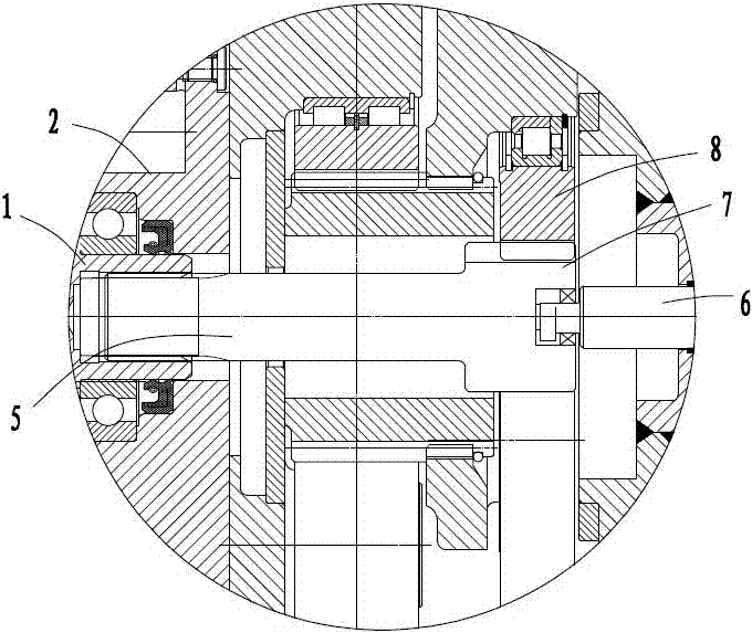
[0026] The hydraulic motor 1 is connected to the reduction device 3 through the telescopic sun gear shaft 5. The left end of the sun gear shaft is splined to the hydraulic motor. The right end of the sun gear shaft is provided with an end hole, and the left end of the tie rod 6 is plugged and fixed in the end hole. The right end of pull rod links to each other with cylinder 14. The sun gear shaft and the pull rod pass through the drum shaft along the axis.

[0027] like ...


PUM


Abstract

The invention relates to a hydraulic winch with a pneumatic clutch, which solves the problems that the existing hydraulic winch clutch structure is complex, unfavorable to running stability and not compact enough. The device includes a frame, which includes a hydraulic motor, a reduction device, and a reel in sequence along the power transmission direction, and is characterized in that: the reduction device is a planetary gear mechanism, and the planetary gear mechanism is at least one stage of planetary gear transmission. The sun gear and the hydraulic motor are connected through the sun gear shaft as power input, and the ring gear is fixed on the inner wall of the reel as power output. A pull rod is connected to the end of the sun gear shaft, and the other end of the pull rod is provided with a cylinder for controlling the stretching of the pull rod. The invention has compact structure, no additional device on the transmission line, and good running stability.

Description

technical field [0001] The invention relates to a winch device, in particular to a hydraulic winch with a pneumatic clutch. Background technique [0002] Ordinary hydraulic winches without clutches need to drive the reel through a hydraulic motor when retracting and releasing the wire rope. When the rescue vehicle needs to tow heavy objects in the distance, if it is an ordinary winch, we need the main system to supply oil to the wire rope. Unwind and drag the wire rope to the heavy object by manpower. This process requires continuous oil supply from the hydraulic system, and the rope unwinding speed is limited by the system flow rate. Especially when the system flow rate is not large, the rope unwinding speed is slow, which affects work efficiency. Therefore, ordinary cars cannot fully meet the above working conditions, but using this hydraulic winch with manual clutch, the clutch working condition of the winch can be realized by operating the joystick. At this time, the mai...

Claims


Application Information

Patent Timeline
Patent Type & Authority Patents(China)
IPC IPC(8): B66D1/14B66D1/08
Inventor 胡亚斌张斌槐孙影王敏敏
Owner INI HYDRAULIC
Why Eureka
Try Eureka