
A manhole cover repair vehicle and automatic milling system

A technology for repairing vehicles and manhole covers, which is applied in road repair, water conservancy projects, artificial islands, etc. It can solve the problems of high labor intensity, low efficiency, and labor-intensive maintenance personnel, so as to ensure intelligence and safety, and improve operational stability. The effect of safety and labor intensity reduction

Active Publication Date: 2018-06-08
武汉市汉福专用车有限公司
View PDF8 Cites 0 Cited by
  • Summary
  • Abstract
  • Description
  • Claims
  • Application Information

AI Technical Summary

Problems solved by technology

There are some manhole covers for urban drainage, communication cables, and power cables distributed on urban roads. Under the repeated action of vehicle loads, the road surface around the manhole covers often breaks and sinks, followed by cracking and damage. Affect traffic safety, road congestion and road beauty, these diseases must be repaired or replaced in order to ensure smooth traffic and driving safety
[0003] At present, there are two solutions, one is the traditional operation, using manual plus small machinery; the other is gradually developed in recent years, using milling mechanism as the main, manual and small machinery as the auxiliary operation method (this kind of operation The method is widely used in Europe and the United States, because the skid loader is used to modify the milling mechanism, the purchase cost and after-sales of accessories are more complicated and costly, and it is rare in China)
These two kinds of operation methods all have the following disadvantages: 1) high noise: such as air compressors, jacks, slitting machines, etc.); 2) the efficiency is not high; 3) the labor intensity of maintenance personnel is high; Waste of materials and high pollution; 5) The construction quality cannot be guaranteed, and vehicle congestion is often caused during the construction period

Method used


Image

  • A manhole cover repair vehicle and automatic milling system
  • A manhole cover repair vehicle and automatic milling system
  • A manhole cover repair vehicle and automatic milling system

Examples


Embodiment Construction

[0021] The following will clearly and completely describe the technical solutions in the embodiments of the present invention with reference to the accompanying drawings in the embodiments of the present invention. Obviously, the described embodiments are only some, not all, embodiments of the present invention. Based on the embodiments of the present invention, all other embodiments obtained by persons of ordinary skill in the art without making creative efforts belong to the protection scope of the present invention.

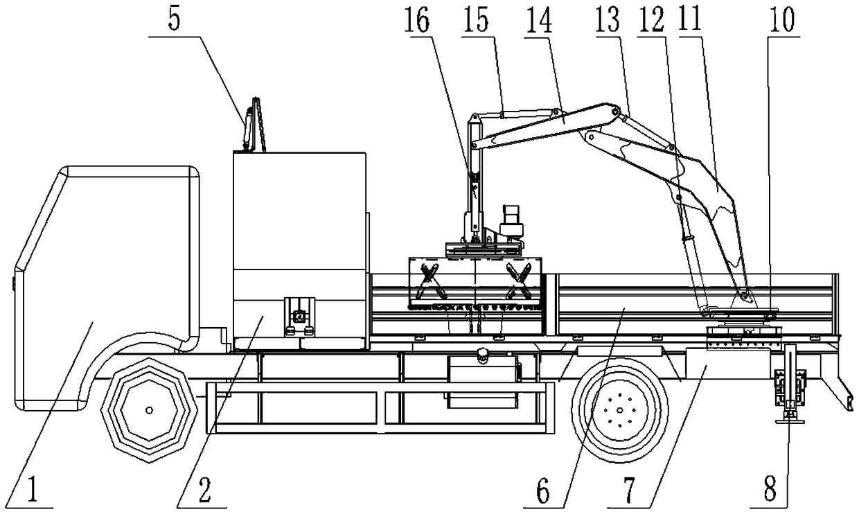
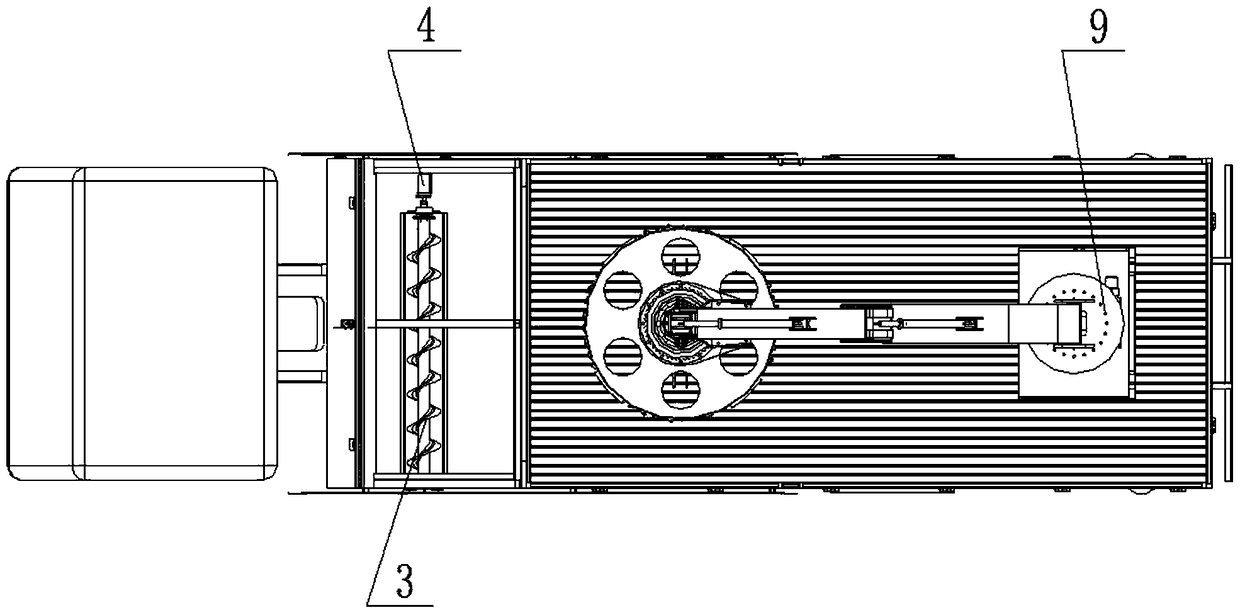
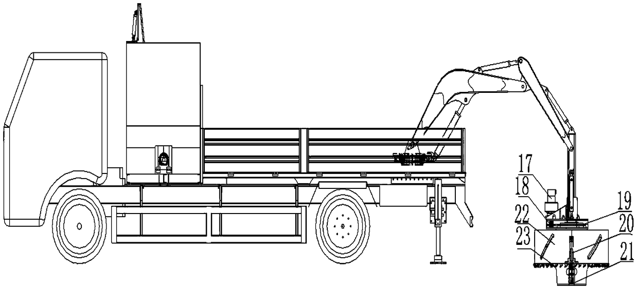
[0022] like Figure 1~3 A manhole cover repair vehicle is shown, including a loading vehicle 1, an asphalt concrete box 2 installed on the loading vehicle, a well cover transport box 6, a control box 7, a boom mechanism, hydraulic support legs 8, a cutter head 22 and a grabbing arm 21 , the loading vehicle 1 is provided with an asphalt concrete box 2, a rotary turntable 9 is installed in the manhole cover transport box 6 at the rear of the loading vehicle 1, a...


PUM


Abstract

The invention discloses a manhole cover repair vehicle, which comprises a loading vehicle, an asphalt concrete box, a well cover transport box, a control box, a boom mechanism, hydraulic support legs, a cutter head and a gripping arm installed on the loading vehicle. There is an asphalt concrete box, and a rotary turntable is installed in the manhole cover transport box at the rear of the loading vehicle. The rotary turntable is connected to a rotary motor, and the rotary motor drives the rotary turntable to rotate; Picking mechanism; the bottom end of the rear of the loading vehicle is provided with hydraulic support legs, hydraulic support legs, slewing motor, boom mechanism, milling mechanism and grabbing mechanism are driven by the hydraulic system, and the hydraulic system is connected to the control box. The invention integrates milling, hoisting and filling of asphalt concrete, replaces manual heavy labor, shortens the maintenance time and cost, and shortens the maintenance time compared with the current road surface damaged manhole cover maintenance norms.

Description

technical field [0001] The invention relates to a manhole cover repair vehicle and an automatic milling system. Background technique [0002] With the development of our country's economy, the traffic volume of highways and urban roads is increasing. Therefore, it is required that the maintenance units of highways and urban roads repair the diseases of highways and urban roads in time and quickly to ensure the normal traffic. There are some manhole covers for urban drainage, communication cables, and power cables distributed on urban roads. Under the repeated action of vehicle loads, the road surface around the manhole covers often breaks and sinks, followed by cracking and damage. Affecting traffic safety, road congestion and road beauty, these diseases must be repaired or replaced in order to ensure smooth traffic and driving safety. [0003] At present, there are two solutions, one is the traditional operation, using manual plus small machinery; the other is gradually de...

Claims


Application Information

Patent Timeline
Patent Type & Authority Patents(China)
IPC IPC(8): E01C23/088E02D29/14
Inventor 谢涛邱声肖彬
Owner 武汉市汉福专用车有限公司
Learn More