Prefabricated column for reverse construction method and underground structure reverse construction method

A construction method and technology for underground structures, applied in the direction of underwater structures, foundation structure engineering, columns, etc., to achieve the effect of enhancing strength and rigidity and eliminating construction procedures

Inactive Publication Date: 2015-12-02
NO 2 CONSTR GRP CO LTD OF SHANGHAI CONSTR GRP
View PDF9 Cites 5 Cited by
  • Summary
  • Abstract
  • Description
  • Claims
  • Application Information

AI Technical Summary

Problems solved by technology

[0005] In view of the troubles of the existing steel lattice column or steel pipe column that need to be back-built concrete construction process, special treatment measures are required for the horizontal joints between the back-build concrete after the column and the concrete of the structural slab poured first, and the existing steel lattice column or steel pipe Due to the insufficient strength of the column, the number of upper construction layers of the upper and lower synchronous reverse construction is limited. The present invention provides a reverse construction method for prefabricated columns and underground structures. By setting annular ribs on the concrete columns of prefabricated columns, the prefabricated The occlusal force between the columns and the structural panels of each layer and the cast-in-place piles ensures a firm connection between the prefabricated columns and the cast-in-situ piles and between the precast columns and the structural panels of each layer, and eliminates the need for back-building of the existing steel lattice columns concrete construction process

Method used


Image

  • Prefabricated column for reverse construction method and underground structure reverse construction method
  • Prefabricated column for reverse construction method and underground structure reverse construction method
  • Prefabricated column for reverse construction method and underground structure reverse construction method

Examples


Embodiment Construction

[0027] The reverse method construction prefabricated column proposed by the present invention will be further described in detail below in conjunction with the accompanying drawings and specific embodiments. Advantages and features of the present invention will be apparent from the following description and claims. It should be noted that all the drawings are in a very simplified form and use imprecise scales, and are only used to facilitate and clearly assist the purpose of illustrating the embodiments of the present invention.

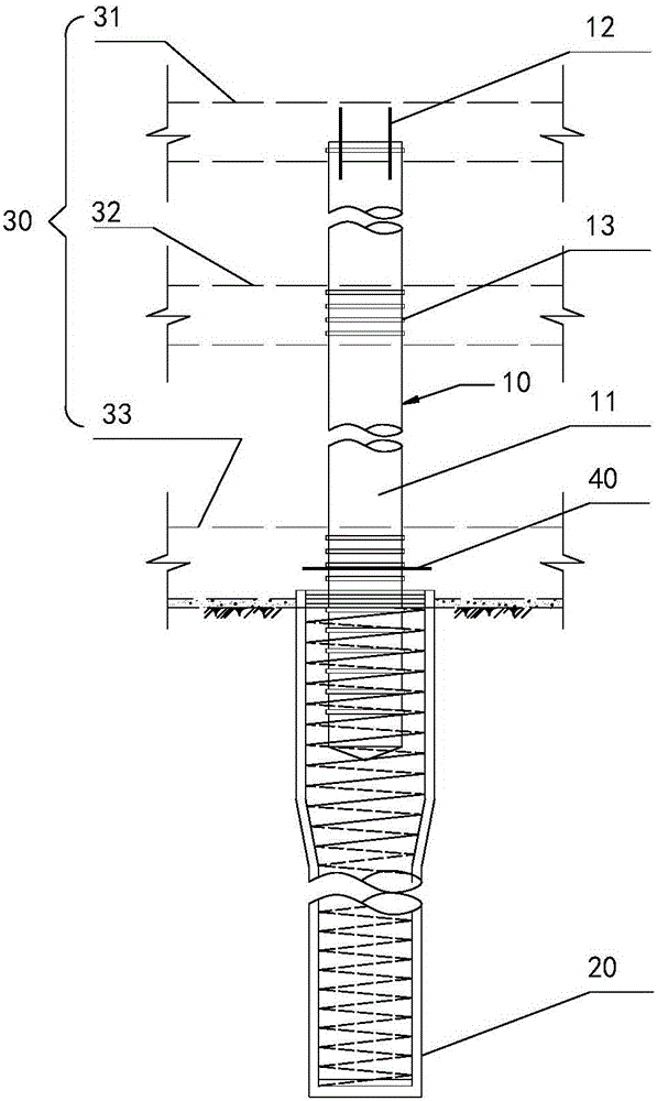
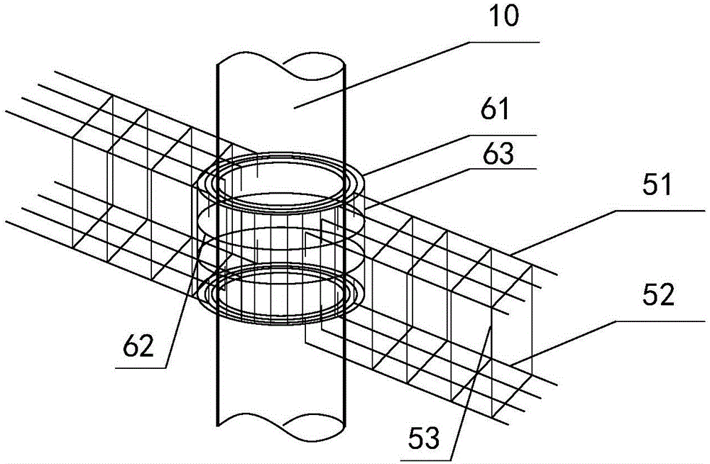
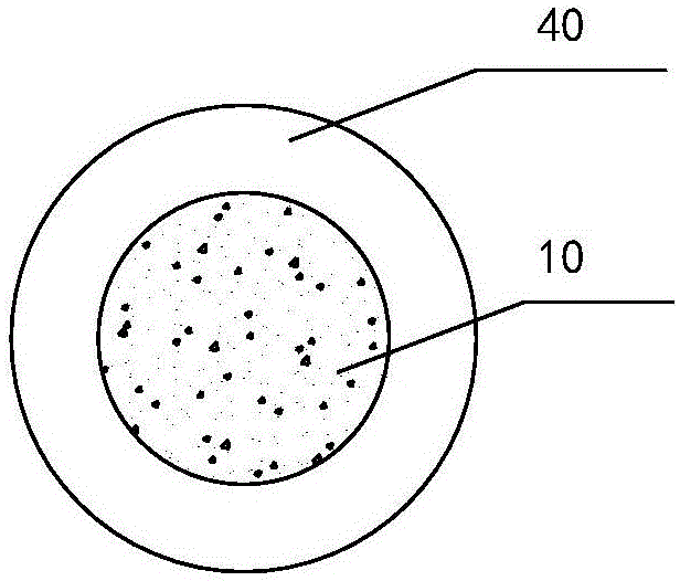
[0028] see Figure 1 to Figure 4 , this embodiment discloses a prefabricated column constructed by the reverse method. The form of the prefabricated column of the present invention is a cylinder as an example (the principle and node form of the rectangular column are similar). The lower part of the prefabricated column 10 extends into the cast-in-situ pile 20, the precast column 10 includes a concrete column body 11, reserved ribs 12 and annular rib...


PUM


Abstract

The invention provides a prefabricated column for a reverse construction method and an underground structure reverse construction method using the prefabricated column. The lower portion of the prefabricated column extends into a bored concrete pile. The prefabricated column comprises a concrete column body, reserved reinforcement and annular ribs, wherein the reserved reinforcement is preset at the top of the column body, and at least one annular rib is disposed on each of the periphery of the part, extending into the bored concrete pile, of the column body and on the periphery of the part, corresponding each layer of structural plate, of the column body. By the annular ribs, the combining force between the prefabricated column and the bored concrete pile and between the prefabricated column and each layer of structural plate can be increased, and accordingly the prefabricated column is firmly connected with the bored concrete pile and each layer of structural plate. In addition, due to the fact that the prefabricated column uses the concrete column body, concrete back construction needed by existing steel-latticework columns is omitted, the strength and rigidity of the prefabricated column, namely a whole beam column system are increased as compared with the steel-latticework columns, and up-down synchronous reverse construction is facilitated.

Description

technical field [0001] The invention relates to the technical field of reverse method construction of building foundation engineering, in particular to a prefabricated column construction technology used for reverse method upright columns. Background technique [0002] Underground engineering construction or deep foundation pit engineering construction can be divided into two types: forward method and reverse method. At present, most projects adopt the straight method of construction, which stabilizes the foundation pit by setting horizontal supports and retaining structures, and then excavates the soil to the design depth to construct the underground structure from bottom to top. [0003] Compared with the straight method of construction, the reverse method has attracted more and more attention because of its advantages in controlling foundation pit deformation, reducing material waste, civilized construction, and overcoming the narrow construction site. During the constru...

Claims


Application Information

Patent Timeline
Patent Type & Authority Applications(China)
IPC IPC(8): E04C3/34E02D29/045E04B1/41
Inventor 马跃强龙莉波高伟
Owner NO 2 CONSTR GRP CO LTD OF SHANGHAI CONSTR GRP
Why Eureka
Try Eureka