Rod-type contact triggering structure of smart home entrance guard device
A smart home, access control technology, applied in building construction, electric alarm locks, building locks, etc., can solve the problem of increasing the probability of false alarms, and achieve the effect of solving wiring problems and increasing practicability
- Summary
- Abstract
- Description
- Claims
- Application Information
AI Technical Summary
Problems solved by technology
Method used
Image

Examples
Embodiment 1
[0023] Example 2
Embodiment 2
[0025] Example 2
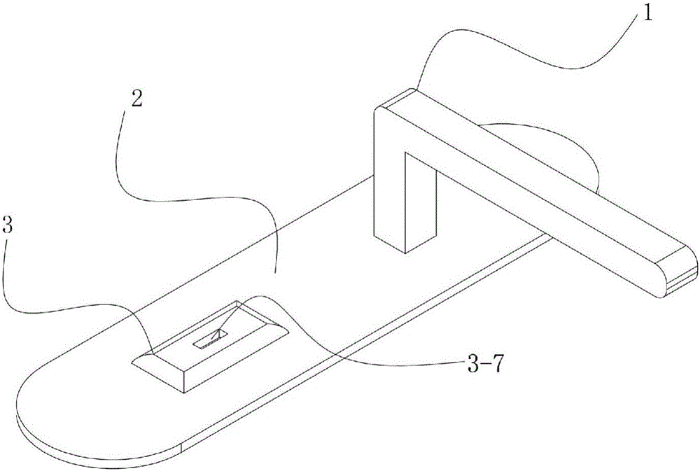
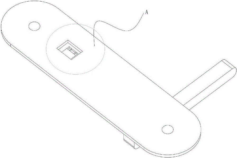
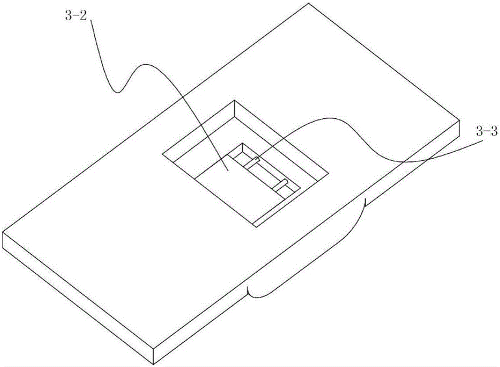
[0026] On the basis of the above-mentioned embodiments, a wire lead-out hole 3-5-1 for leading out the electrode contacts 3-6-2 is provided in the rear cover mounting cavity 3-5. The electrode contacts are embedded on both sides of the inner wall of the rectangular cavity 3-6, and the wires are connected to the motor contacts through the wire lead-out hole 3-5-1, so that the electrodes can be easily led out, avoiding the space occupied by other lead wires.
[0027] Example 3
Embodiment 3
[0029] The 555 timer is a medium-scale integrated device that combines analog circuits and digital circuits. It has excellent performance and a wide range of applications. A small amount of resistance-capacitance components can be connected externally to form a monostable trigger and multivibrator. It can also form a Schmitt trigger without external components. It is often used as a timer and is widely used in instrumentation, household appliances, electronic measurement and automatic control. The interior of the 555 timer includes two voltage comparators, three equivalent series resistors, an RS flip-flop, a discharge tube T and a power output stage. It provides two reference voltages VCC / 3 and 2VCC / 3. Therefore, the integrated 555 timing is widely used in the generation and transformation of pulse waveforms, measurement and control, etc.
[0030] To alarm, there must be a trigger signal, which can be triggered by the opening or closing of the switch. A 555 time base circuit...
PUM
 Abstract
Description
Claims
Application Information
 - Generate Ideas
- Intellectual Property
- Life Sciences
- Materials
- Tech Scout
- Unparalleled Data Quality
- Higher Quality Content
- 60% Fewer Hallucinations
Browse by: Latest US Patents, China's latest patents, Technical Efficacy Thesaurus, Application Domain, Technology Topic, Popular Technical Reports.
© 2025 PatSnap. All rights reserved.Legal|Privacy policy|Modern Slavery Act Transparency Statement|Sitemap|About US| Contact US: help@patsnap.com