A heat insulation method and device for a cylinder

A heat insulation device, cylinder technology, applied in the direction of engine components, machines/engines, mechanical equipment, etc., can solve problems such as threats to lubricating oil quality

Active Publication Date: 2016-08-17
JIANGSU HUADIAN YIZHENG THERMOELECTRICITY CO LTD
View PDF6 Cites 0 Cited by
  • Summary
  • Abstract
  • Description
  • Claims
  • Application Information

AI Technical Summary

Problems solved by technology

The high temperature at the front steam seal transmits heat to the front box through heat radiation, which poses a potential threat to the quality of lubricating oil

Method used


Image

  • A heat insulation method and device for a cylinder
  • A heat insulation method and device for a cylinder

Examples


Embodiment 1

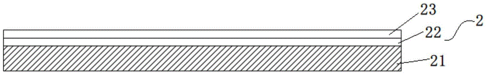
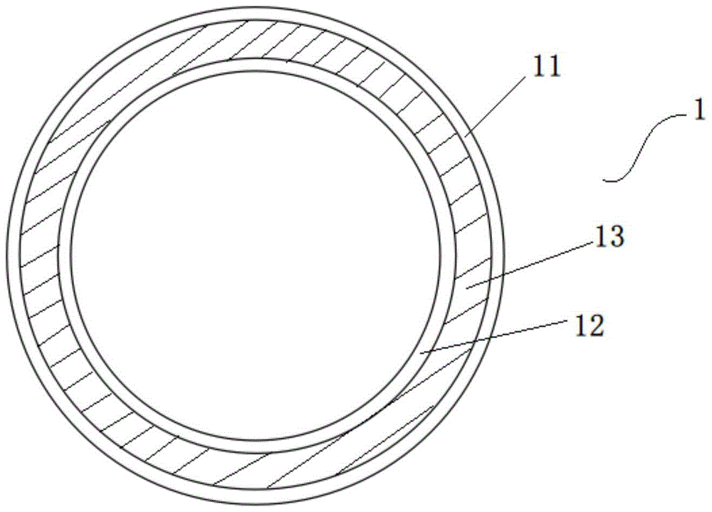
[0030] Example 1: figure 1 It is a schematic cross-sectional view of the heat insulation cover for the cylinder heat insulation device provided by the embodiment of the present invention, figure 2 It is a schematic cross-sectional view of the heat insulation board of the heat insulation device for the cylinder provided by the embodiment of the present invention. It can be clearly seen from the figure that the heat insulation device for the cylinder provided by this embodiment includes a heat insulation cover 2 and a heat insulation cover 2. plate 1, the heat preservation cover 2 is fixedly laid on the outer surface of the cylinder, the heat preservation cover 2 includes a heat preservation layer 21 and a plastering layer, the heat preservation layer 21 is arranged on the inner side of the heat preservation cover 2, preferably, the heat preservation cover The thermal insulation layer 21 of 2 is the aluminum silicate needle-punched blanket of long-fiber needle-punched formation...

Embodiment 2

[0045] Example 2: figure 1 It is a schematic cross-sectional view of the heat insulation cover for the cylinder heat insulation device provided by the embodiment of the present invention, figure 2 It is a schematic cross-sectional view of the heat insulation board of the heat insulation device for the cylinder provided by the embodiment of the present invention. It can be clearly seen from the figure that the heat insulation device for the cylinder provided by this embodiment includes a heat insulation cover 2 and a heat insulation cover 2. plate 1, the heat preservation cover 2 is fixedly laid on the outer surface of the cylinder, the heat preservation cover 2 includes a heat preservation layer 21 and a plastering layer, the heat preservation layer 21 is arranged on the inner side of the heat preservation cover 2, preferably, the heat preservation cover The thermal insulation layer 21 of 2 is the aluminum silicate needle-punched blanket of long-fiber needle-punched formation...


PUM


Abstract

The invention relates to the field of turbines, and discloses a heat insulation method for a cylinder. The method includes the steps of performing heat insulation treatment on the exposed cylinder and arranging a heat insulation board on a front bearing pedestal corresponding to the cylinder. The process of performing heat insulation treatment on the exposed cylinder includes the steps that S11, a heat insulation layer is laid on the outer surface of the cylinder; S12, a metal wire net is laid on the outer surface of the heat insulation layer; S13, asbestos powder, cement powder and plastering powder are mixed and added with water to be stirred to form plastering slurry; S14, the plastering slurry is applied on the metal wire net and the heat insulation layer to form a first plastering layer; S15, after the moisture of the first plastering layer is reduced by 60%-80%, surface slurry is applied on the first plastering layer to form a second plastering layer. The invention further discloses a heat insulation device for the cylinder. According to the heat insulation method for the cylinder, heat insulation treatment is performed on the exposed cylinder at a front steam seal, so that heat is prevented from being emitted outwards; meanwhile, the baffle is installed at an oil catch of the front bearing pedestal, so that influences of heat radiation are further reduced.

Description

technical field [0001] The invention relates to the field of steam turbines, in particular to a heat insulation method and device for a cylinder. Background technique [0002] A steam turbine is a rotary power machine that converts the energy of steam into mechanical work. After the steam from the boiler enters the steam turbine, it passes through a series of annular nozzles and movable blades in turn to convert the thermal energy of the steam into the mechanical energy of the rotor rotation of the steam turbine. It is a modern The most widely used prime mover in thermal power plants. The gap between the rotor and the static body will cause steam leakage, which will not only reduce the efficiency of the unit, but also affect the safe operation of the unit. In order to prevent steam leakage and air leakage, a sealing device is required, commonly known as a steam seal. [0003] At present, the temperature of the front air seal of the steam turbine exceeds the standard. Accor...

Claims


Application Information

Patent Timeline
Patent Type & Authority Patents(China)
IPC IPC(8): F01D25/08
Inventor 莫俊武周军曹康程斌袁亮亮
Owner JIANGSU HUADIAN YIZHENG THERMOELECTRICITY CO LTD
Why Eureka
Try Eureka