Automatic double-gear transmission

A technology of automatic transmission and driven gear, which is applied in the direction of instruments, transmission devices, transmission device control, etc. It can solve the problems of driver's frustration, large impact of synchronous lock ring and gear outer cone surface, cumbersome operation, etc., and achieve smooth operation Reduced irritation, reduced frustration, and easy operation

Active Publication Date: 2015-12-02
CHONGQING UNIV
View PDF5 Cites 3 Cited by
  • Summary
  • Abstract
  • Description
  • Claims
  • Application Information

AI Technical Summary

Problems solved by technology

[0003] However, this structure that achieves synchronization by friction will cause a large impact on the synchronous lock ring and the outer cone surface of the gear, and serious wear; and this synchronous t

Method used


Image

  • Automatic double-gear transmission
  • Automatic double-gear transmission
  • Automatic double-gear transmission

Examples


Embodiment Construction

[0026] The present invention will be further described below with reference to the drawings and embodiments, but it should not be understood that the scope of the above subject matter of the present invention is limited to the following embodiments. Without departing from the above-mentioned technical idea of ​​the present invention, various substitutions and changes based on common technical knowledge and conventional means in the field shall be included in the protection scope of the present invention.

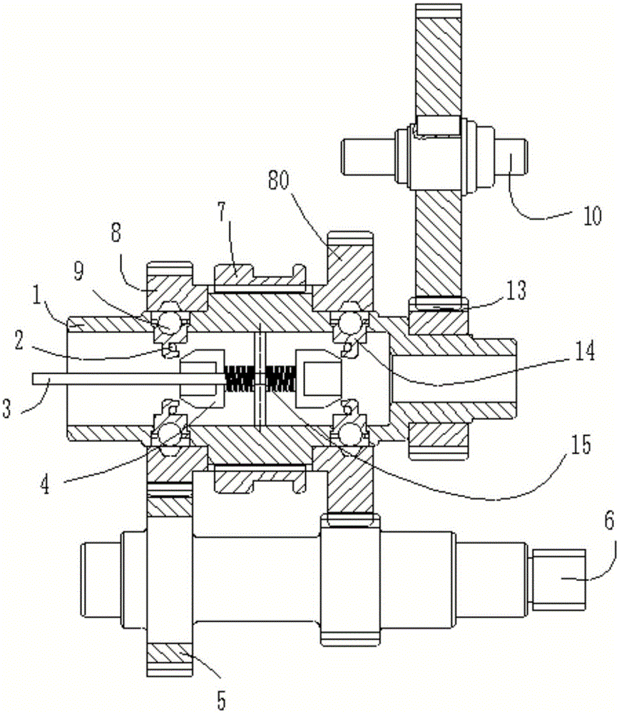
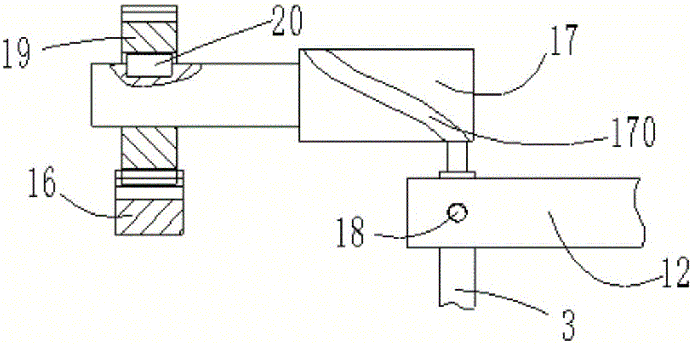
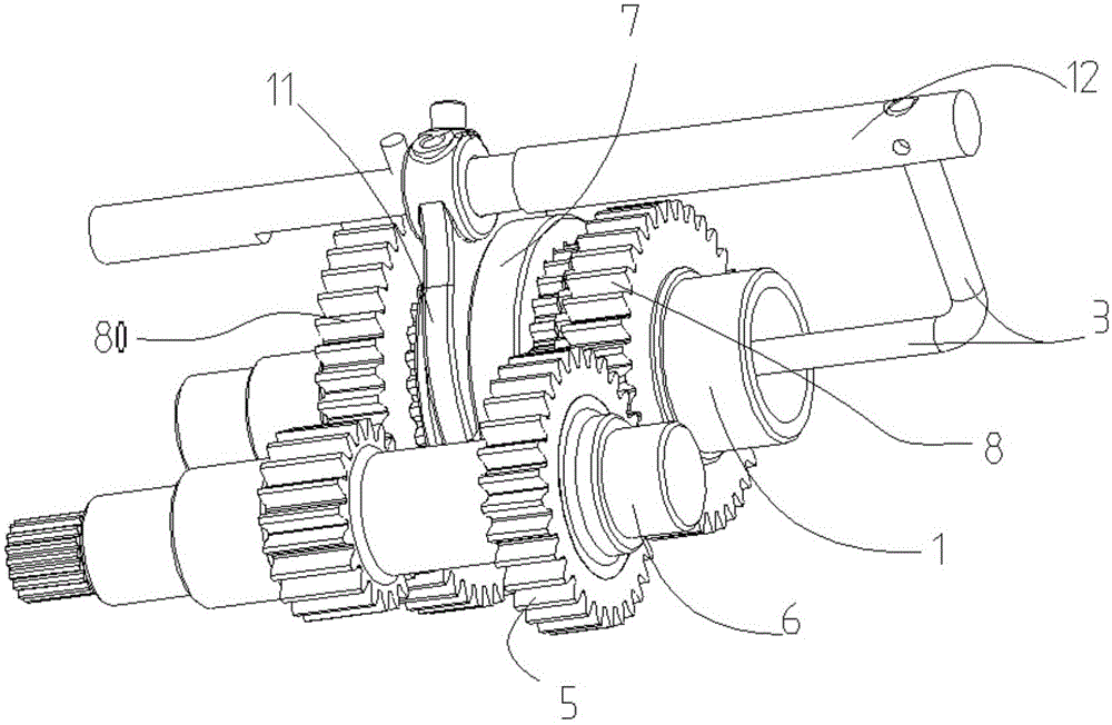
[0027] A two-speed automatic transmission, including a hollow shaft 1, a spring ring 2, a boss push rod 3, a movable boss 4, a driving gear 5, an input shaft 6, a coupling sleeve 7, a driven gear Ⅰ 8, a driven gear Ⅱ 80, steel Ball 9, output shaft 10, shift fork 11, shift fork shaft 12, transmission gear set 13, steel ball holder 14, spring 15, rack 16, cylindrical cam 17, bolt 18, gear 19 and ordinary flat key 20.

[0028] See Figure 5 The hollow shaft 1 is a stepped shaft with...


PUM


Abstract

The invention discloses an automatic double-gear transmission and provides a power-failure-free mechanical transmission integrating flexible transmission with rigid transmission. The automatic double-gear transmission comprises a hollow shaft, spring rings, a boss push rod, a movable boss, a driving gear, an input shaft, an engagement sleeve, a driven gear I, a driven gear II, steel balls, an output shaft, a shifting fork, a shifting fork shaft, a transmission gear set and steel ball racks; the boss push rod is installed in the center of the hollow shaft; the boss push rod is connected with the shifting fork shaft through a bolt so that the linkage between the boss push rod and the shifting fork shaft can be achieved, and therefore the movable boss and the engagement sleeve are driven to move in the axial direction. According to the transmission, the gear shifting process is simple to operate, the ectrosis sense is not obvious, and impact, collision and friction in the connection process can be reduced effectively.

Description

Technical field [0001] The invention relates to the field of mechanical transmission, in particular to a two-speed mechanical transmission suitable for low-power electric vehicles. Background technique [0002] At present, inertial synchronizers are used in most synchronous transmissions, which are mainly composed of coupling sleeves, synchronization lock rings, etc., which mainly rely on friction to achieve synchronization. When the inner cone surface of the synchronizing lock ring contacts the outer cone surface of the gear ring to be joined, the gear speed is rapidly reduced (or increased) under the action of the friction torque to be equal to the speed of the synchronizing lock ring, and the two rotate synchronously, and the gear relative to The rotation speed of the synchronizing lock ring is zero, so the moment of inertia disappears at the same time. At this time, driven by the force, the coupling sleeve is unimpededly engaged with the synchronizing lock ring gear ring, and...

Claims


Application Information

Patent Timeline
IPC IPC(8): F16H63/32F16H3/087
CPCF16H3/087F16H63/32
Inventor 李聪波胡捷李月肖卫洪赵来杰单亚帅陈文倩
Owner CHONGQING UNIV
Why Eureka
Try Eureka