
Backlight module and display device

A backlight module, green light technology, applied in identification devices, lighting devices, fixed lighting devices, etc., can solve the problems of inability to mass-produce products, reducing optical performance, and immaturity of quantum dot light-emitting diodes

Active Publication Date: 2015-12-02
BOE TECH GRP CO LTD +1
View PDF4 Cites 22 Cited by
  • Summary
  • Abstract
  • Description
  • Claims
  • Application Information

AI Technical Summary

Problems solved by technology

Among them, the quantum dot film is the function of replacing the diffusion sheet with the quantum film. A layer of quantum dot film covering the entire display area is added to the light guide plate. White light output, but the uniformity of distribution of quantum dot materials in the quantum dot film is difficult to control, quantum dot materials are easily affected by water vapor and oxygen in the environment, resulting in reduced luminous characteristics, so the mass production of corresponding products is not high; quantum dots Light-emitting diodes distribute quantum dot particles in the encapsulant of light-emitting diodes, but due to the problem of weak bonding between quantum dot particles and resin, and the fact that quantum dots may agglomerate inside the encapsulant during the encapsulation process, this will affect the actual The light-emitting condition of the light-emitting diode reduces the optical performance, and the current production technology of quantum dot light-emitting diodes is not yet mature, and the corresponding products are limited to the development stage and cannot be mass-produced; quantum dot tubes are added between the blue light-emitting diode and the light guide plate. Layered quantum dot structure, the blue light-emitting diode excites the quantum dot structure and finally converts it into white light output. In this scheme, the blue light-emitting diode occupies more frame positions, so this scheme has a certain impact on the narrow frame

Method used


Image

  • Backlight module and display device
  • Backlight module and display device
  • Backlight module and display device

Examples


Embodiment Construction

[0027] The specific implementation manners of the backlight module and the display device provided by the embodiments of the present invention will be described in detail below with reference to the accompanying drawings.

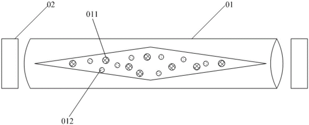
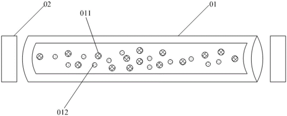
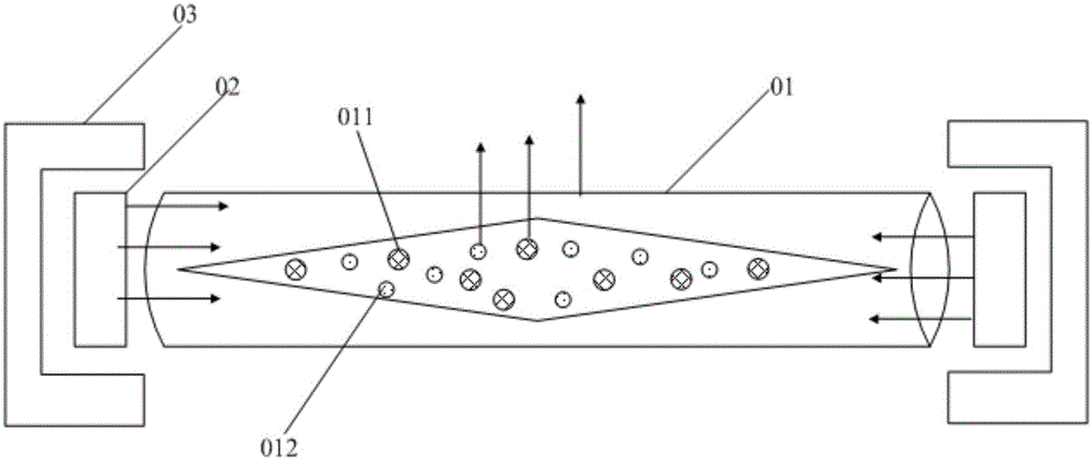
[0028] An embodiment of the present invention provides a backlight module, such as figure 1 As shown, it may include: a glass cavity 01 and a blue light-emitting diode 02; wherein,

[0029] Red light quantum dot material 011 and green light quantum dot material 012 are encapsulated in the glass cavity 01, and a blue light-emitting diode 02 is respectively arranged at both ends of the glass cavity 01;

[0030] The red light quantum dot material 011 and the green light quantum dot material 012 in the glass cavity 01 respectively emit red light and green light correspondingly after being excited by the light emitted by the blue light emitting diode 02 .

[0031] The above-mentioned backlight module provided by the embodiment of the present invention includes...


PUM


Abstract

The invention discloses a backlight module and a display device. The backlight module comprises a glass cavity and blue light-emitting diodes. The glass cavity is internally provided with red light quantum dot material and green light quantum dot material in a packaging mode. The two ends of the glass cavity are each provided with one blue light-emitting diode. The red light quantum dot material and green light quantum dot material in the glass cavity correspondingly emit red light and green light after being excited by light emitted by the blue light-emitting diodes. In this way, the quantum dot material is arranged in the glass cavity in the packaging mode, the two ends of the glass cavity are each provided with one blue light-emitting diode, and the quantum dot material correspondingly emits red light and green light after being excited by the light emitted by the blue light-emitting diodes, so that the red light and the green light are mixed with blue light reflected by the surface of the glass cavity to form white background light, the function of a backlight source is achieved; besides, the two ends of the glass cavity are provided with the blue light-emitting diodes serving as excitation light sources, and narrow frame design of the display device is facilitated.

Description

technical field [0001] The invention relates to the field of display technology, in particular to a backlight module and a display device. Background technique [0002] At present, by utilizing the luminescent properties of quantum dots, quantum dots can be used as molecular probes in fluorescent labels, and can also be used in display devices, using monochromatic quantum dots as the light source of backlight modules. After being excited by the light emitted by the color light-emitting diode, it emits monochromatic light mixed with blue light to form a white background light, which has a large color gamut and can improve the picture quality. [0003] Quantum dots are the main technical development direction of high color gamut products. The main implementation methods of high color gamut backlights using quantum dots include quantum dot films, quantum dot tubes and quantum dot light-emitting diodes. Among them, the quantum dot film is the function of replacing the diffusion...

Claims


Application Information

Patent Timeline
IPC IPC(8): F21S8/00G09F9/00H01L33/50F21Y101/02
CPCF21S8/00G09F9/00H01L33/50
Inventor 石海军朴仁镐刁凯
Owner BOE TECH GRP CO LTD
Learn More