A kind of air duct return air outlet

A return air outlet and air duct technology, which is applied in the field of air return air duct, can solve the problems affecting the return air efficiency and achieve the effect of improving the return air efficiency and reducing the inlet vortex

Active Publication Date: 2018-07-31
HEFEI HUALING CO LTD +1
View PDF8 Cites 0 Cited by
  • Summary
  • Abstract
  • Description
  • Claims
  • Application Information

AI Technical Summary

Problems solved by technology

[0003] The invention provides an air return port of an air duct. The technical problem to be solved is that when the fan rotates at a high speed in the traditional return air port, a local vortex will be formed at the return air port, which will affect the return air efficiency.

Method used


Image

  • A kind of air duct return air outlet
  • A kind of air duct return air outlet
  • A kind of air duct return air outlet

Examples


Embodiment Construction

[0026] The principles and features of the present invention are described below in conjunction with the accompanying drawings, and the examples given are only used to explain the present invention, and are not intended to limit the scope of the present invention.

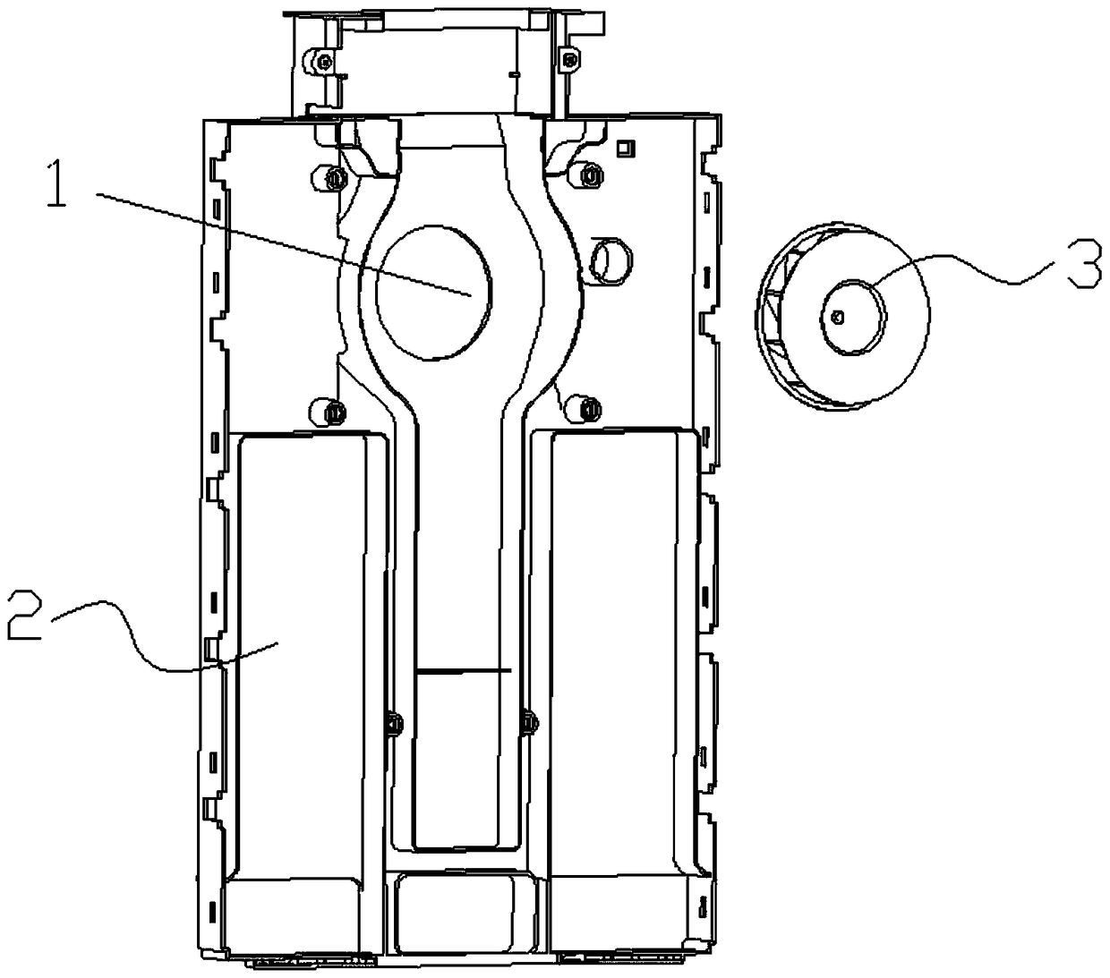
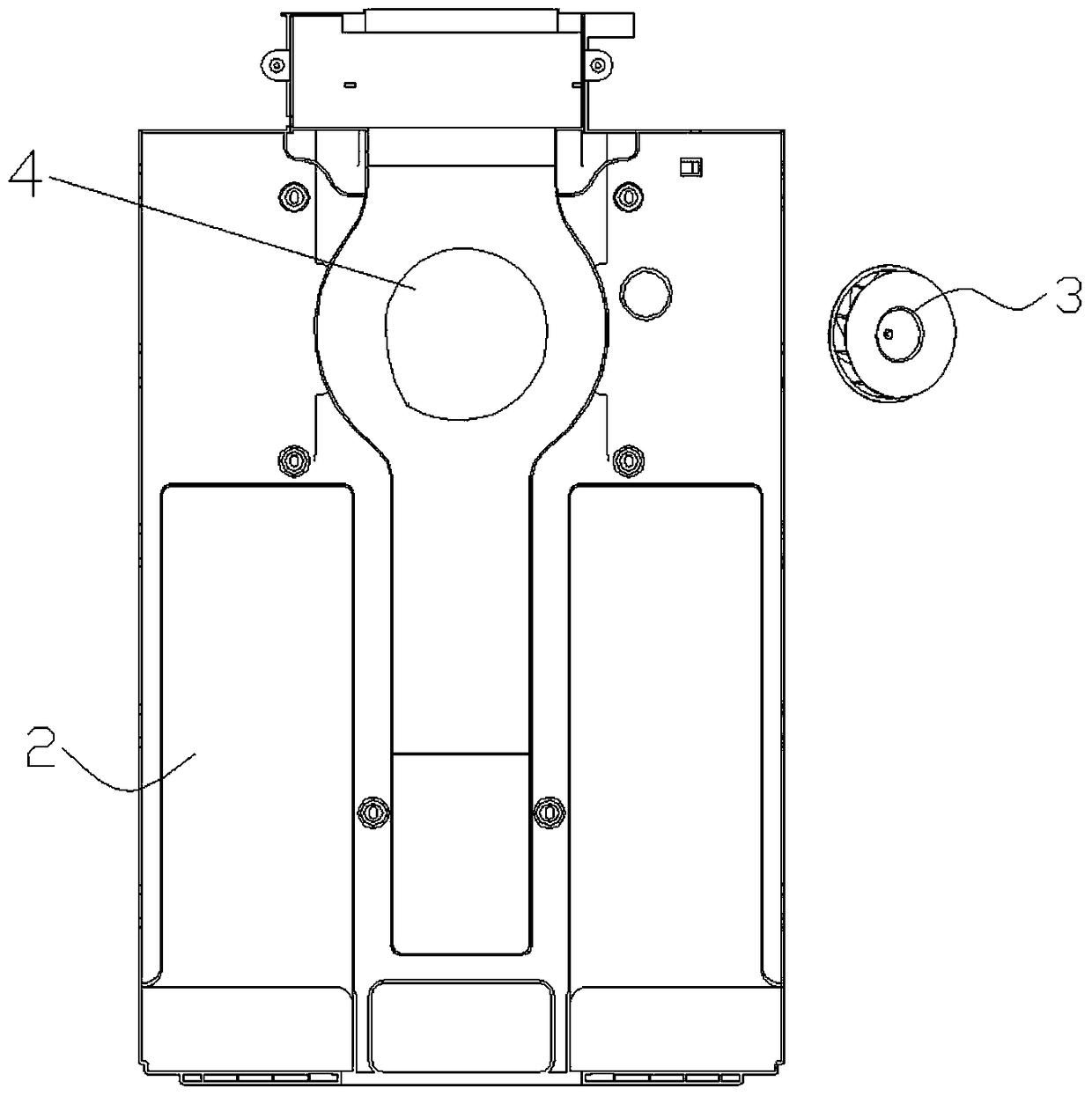
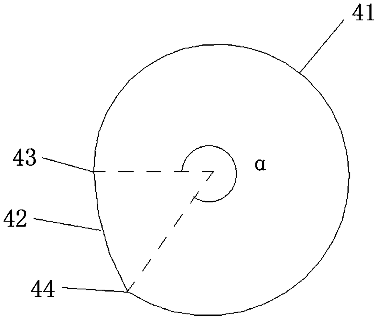
[0027] Such as image 3 As shown, the present invention provides an air duct return air outlet 4, the air duct return air opening 4 is arranged at one end of the air channel 2 in the air duct, and a fan is provided in the gas channel 2 and opposite to the air duct return air opening 4 3. The shape of the air return port 4 of the air duct is a non-circular closed curve composed of a section of Archimedes spiral 41 and a section of arc 42 connected end to end, wherein the expansion direction of the Archimedes spiral 41 is the same as that of the fan. The fan blades of 3 turn to the opposite; the center of rotation of the Archimedes spiral 41 coincides with the projection point of the center of the fan 3 on the plane w...


PUM


Abstract

The invention relates to a return air inlet of an air duct. The return air inlet of the air duct is arranged in one end of an air channel of the air duct. A fan is arranged in the position, opposite to the return air inlet of the air duct, in the air channel. The shape of the return air inlet of the air duct is a non-round closed curve formed by connecting an Archimedes spiral line and an arc in an end-to-end mode, wherein the expansion direction of the Archimedes spiral line is opposite to the rotation direction of blades of the fan. The area of the return air inlet of the air duct is larger than that of an original return air inlet of an air duct, the diameter of the return air inlet of the air duct is gradually decreased in the acceleration direction of the blades to airflow, inlet acceleration of the airflow can be better facilitated, and therefore the air return efficiency is improved. In addition, the return air inlet of the air duct is closer to the return airflow direction, inlet vortexes are reduced easily and the air return efficiency is improved.

Description

technical field [0001] The invention relates to the field of ventilation, in particular to an air return port of an air duct. Background technique [0002] Such as figure 1 As shown, in general, the air duct is composed of a gas channel 2, a return air outlet 1 and an air supply port communicating with the gas channel, and in the gas channel and at a position opposite to the return air outlet 1, there is a fan3. However, the existing return air inlet 1 is usually circular, and when the fan rotates at high speed, a local vortex will be formed at the return air inlet, which affects the return air efficiency. Contents of the invention [0003] The invention provides a return air outlet of an air duct, and the technical problem to be solved is that when the fan rotates at a high speed in the traditional air return outlet, a local vortex will be formed at the return air outlet, which affects the return air efficiency. [0004] The technical scheme that the present invention ...

Claims


Application Information

Patent Timeline
Patent Type & Authority Patents(China)
IPC IPC(8): F24F13/06F24F7/06
CPCF24F7/065F24F13/06
Inventor 陆彭飞吴国富
Owner HEFEI HUALING CO LTD
Why Eureka
Try Eureka