Industrial ct scanning machine synchronous loading test device and industrial ct scanning machine

A loading test device and CT scanning technology, applied in the direction of material analysis using radiation, can solve the problems of low ray power, inability to scan engineering material specimens, and failure to meet the detection requirements of conventional engineering materials, etc., to achieve loading oil pressure constant effect

Active Publication Date: 2017-08-08
RES INST OF HIGHWAY MINIST OF TRANSPORT +2
View PDF7 Cites 0 Cited by
  • Summary
  • Abstract
  • Description
  • Claims
  • Application Information

AI Technical Summary

Problems solved by technology

[0004] At present, there is no synchronous loading device specially developed for industrial CT scanners. Some research institutions have developed loading equipment for medical CT scanners. , the strength is lower than 40kv) cannot scan the engineering material specimens with high density, and the ray penetration ability is limited, which can only meet the scanning and flaw detection of specimens with a diameter of less than 5cm, and cannot meet the detection requirements of conventional engineering materials. The radiation intensity of industrial CT scanners exceeds 200kv, which can meet the scanning and flaw detection requirements of civil engineering materials with a diameter of more than 10cm
On the other hand, the images acquired by medical CT scanners are reconstructed based on the characteristics of the human body. The threshold segmentation and pattern recognition of the images are not suitable for civil engineering materials, and the program is difficult to carry out secondary development.

Method used


Image

  • Industrial ct scanning machine synchronous loading test device and industrial ct scanning machine
  • Industrial ct scanning machine synchronous loading test device and industrial ct scanning machine
  • Industrial ct scanning machine synchronous loading test device and industrial ct scanning machine

Examples


Embodiment Construction

[0040] The present invention will be described in further detail below in conjunction with the accompanying drawings.

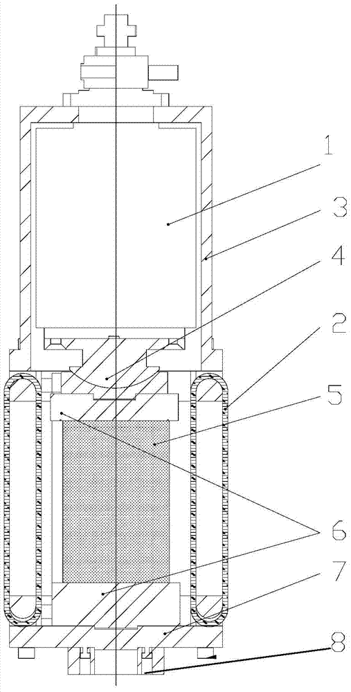
[0041] As shown in Figure 1, the industrial CT scanning machine synchronous loading test device includes a single-acting rotary loading cylinder 1, a see-through carbon fiber reaction force frame 2, a micro-torque rotating mechanism, a hydraulic loading system and a pressure display system;

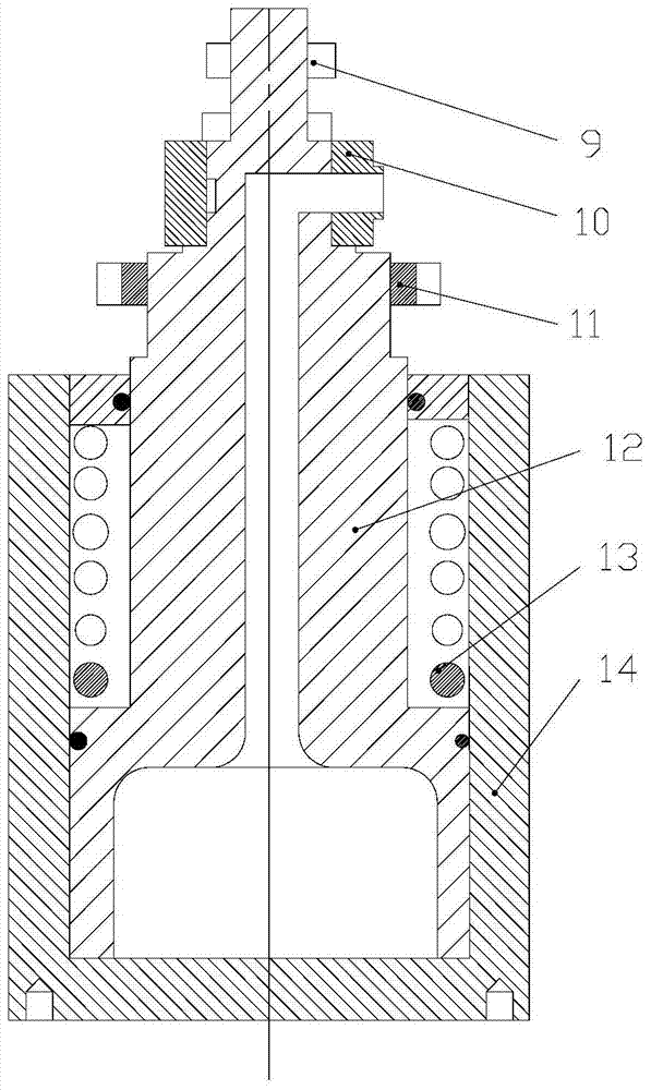
[0042] Such as figure 2 As shown, the single-acting rotary loading oil cylinder includes a rotary oil connection port 10, a cylinder body 12, a reaction force spring 13 located in the oil cylinder body 12, and a cylinder piston 14, and the rotary oil connection port 10 is sleeved on the cylinder piston 14, the outside of the rotary oil port 10 is connected to the oil source, and the inside is connected to the oil cylinder body 12. The rotary oil port 10 and the cylinder piston 14 can rotate relatively. The oil cylinder piston 14 is located on the upper part of the oil c...


PUM


Abstract

The invention relates to a synchronous loading test device for an industrial CT scanning machine and an industrial CT scanning machine, belonging to the field of test and detection equipment. The device includes a single-acting rotary loading cylinder, a see-through carbon fiber reaction frame, a micro-torque rotating mechanism, an oil pressure loading system and a pressure display system; The oil port, the see-through carbon fiber reaction frame includes an upper connection frame and a lower connection plate, and a carbon fiber support wound between the upper connection frame and the lower connection plate, and the test piece is located between the upper connection frame and the lower connection plate. The single-acting rotary loading cylinder and the see-through carbon fiber reaction frame together form a self-reflexive force mechanism. The see-through carbon fiber reaction frame has almost no absorption of X-rays, and the rays pass through the carbon fibers to irradiate the specimen without energy loss. The invention works together with an industrial CT scanning machine, can realize loading on a test piece, and can perform real-time scanning on changes such as damage of the test piece.

Description

technical field [0001] The invention is mainly used to realize the matching loading of industrial CT scanning machines, and is specially designed to study the damage and destruction mechanism of civil engineering materials, and realize the purpose of collecting CT tomographic images in real time during the loading and damage process of materials, and belongs to civil engineering material test equipment field. Background technique [0002] In recent years, the use of industrial CT scanners to non-destructively collect and analyze the internal mesoscopic composition and damage mechanism of materials has gradually become one of the important technical means for civil engineering materials research. The basic principle is to penetrate the measured object through the radiation emitted by the industrial CT machine, and through the attenuation law of the radiation energy, reconstruct and calculate to form an image to analyze the composition and structure. However, since the indust...

Claims


Application Information

Patent Timeline
Patent Type & Authority Patents(China)
IPC IPC(8): G01N23/04
Inventor 张蕾王旭东周兴业彭司卉肖倩单伶燕刘博彭京武
Owner RES INST OF HIGHWAY MINIST OF TRANSPORT
Why Eureka
Try Eureka