Alignment angle detection apparatus and detection method

An angle detection and alignment technology, applied in measurement devices, optical devices, optics, etc., can solve problems such as production efficiency decline, production capacity loss, and inability to produce batches to be shipped, so as to improve production efficiency and avoid production capacity losses. Effect

Active Publication Date: 2015-12-02
KUSN INFOVISION OPTOELECTRONICS
View PDF6 Cites 5 Cited by
  • Summary
  • Abstract
  • Description
  • Claims
  • Application Information

AI Technical Summary

Problems solved by technology

[0006] However, when the experimental batch is put into production, it needs to go through the alignment process and ODF (One Drop Fill) process, and then use the inspection machine to detect the alignment angle of the experimental batch, so as to make corresponding adjustments to the process parameters of the shipping batch before proceedin

Method used


Image

  • Alignment angle detection apparatus and detection method
  • Alignment angle detection apparatus and detection method

Examples


Example Embodiment

[0019] In order to make the purpose, technical solution and advantages of the present invention clearer, the embodiments of the present invention will be further described in detail below in conjunction with the accompanying drawings.

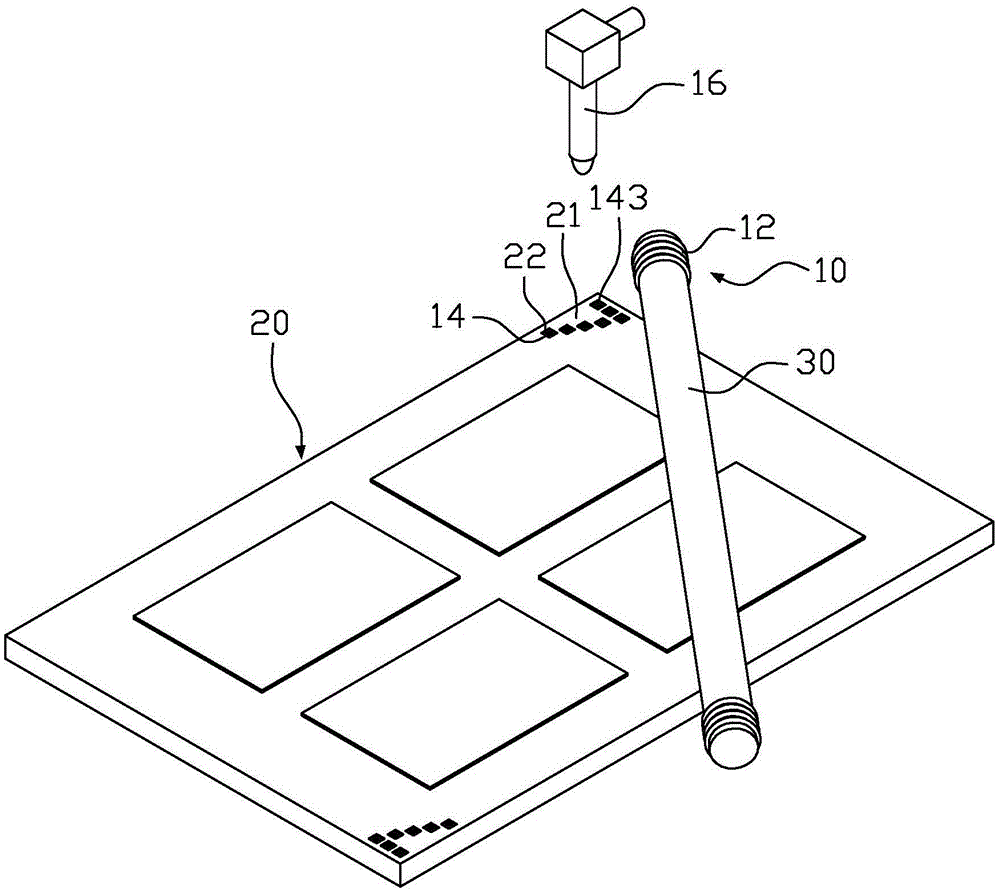
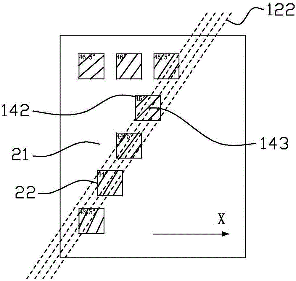
[0020] figure 1 is a schematic structural diagram of an alignment angle detection device according to an embodiment of the present invention, figure 2 Yes figure 1 A partial enlargement of the . For the convenience of description, figure 1 In addition to the alignment angle detection device 10, it also includes a substrate motherboard 20 formed with a PI layer and an alignment roller shaft 30, please refer to figure 1 As shown, the alignment angle detection device 10 of the present invention includes a marking structure 12 , a standard angle comparison unit 14 , and an image controller 16 .

[0021] The marking structure 12 is a ring-shaped protruding structure, and the marking structure 12 is coaxially sleeved on the end of the alignment ...


PUM


Abstract

The invention provides an alignment angle detection apparatus comprising a marking unit and a standard angle comparison part. The marking unit has an annular protrusion structure, and is coaxially arranged at the end portion of an alignment roll shaft in a sleeving manner. The standard angle comparison part is arranged on the blank zone of a substrate motherboard provided with a PI layer. When the alignment roll shaft rolls for alignment, the marking unit is in contact with the blank zone and draws a trace line in the blank zone through scratching, and the trace line and the standard angle comparison part are compared so as to determine the angle value of the trace line. The invention also provides an alignment angle detection method by the use of the alignment angle detection apparatus.

Description

technical field [0001] The invention relates to the technical field of liquid crystal display panels, in particular to an alignment angle detection device and detection method. Background technique [0002] With the rapid development of electronic products towards lightness, thinness and miniaturization, almost all kinds of portable electronic products use liquid crystal displays (Liquid Crystal Display, LCD) as display terminals, especially in camcorders, notebook computers, desktop computers, In products such as smart TVs, mobile terminals or personal digital processors, liquid crystal displays have become an important component of electronic products. [0003] The liquid crystal display mainly includes a liquid crystal panel and a backlight module, wherein the liquid crystal panel includes a thin film transistor (ThinFilmTransistor, TFT) substrate and a color filter (ColorFilter, CF) substrate formed in a box, and a liquid crystal layer filled therebetween. [0004] In t...

Claims


Application Information

Patent Timeline
IPC IPC(8): G02F1/1337G02F1/13G01B11/26
CPCG01B11/26G02F1/1309G02F1/1337
Inventor 孙淑丁
Owner KUSN INFOVISION OPTOELECTRONICS
Why Eureka
Try Eureka